Climate Odyssey
Brief
Create a game aimed at 11-15 year old school children to encourage and teach climate protection.
Goal
Create a wave game where an eco stable robot uses a solar powered wepon to eliminate monsters that have an impact in climage change.
Role in Project
Designer
3D Artist
Unity Developer
Software
Blender 2.90
Illustrator CC
Unity
Preperation
Research
Sketches & planning
Robot
1.1 Basic Construct
1.2 Key Parts
1.3 Rigging & Armature
1.4 Arm Development
1.5 Leg Development
Robot
1.6 Kinematics
1.7 Vertext Groups & Weight Painting
1.8 Robot Animations
Solar Powered Gun
1.9 Gun Sketches
1.10 Modeling
1.11 Animating
Research
Game Plan & Engagement
Game Plan
Our game is called Climate Odyssey, a game which is focused on protecting the trees within a small environment from climate related monsters.
The player will spawn on a floating island that will contains trees, a river and general assets such as small mountains and rocks. The player themselves would be playing as an Eco-Friendly Robot that will be equipped with a Solar Powered Gun.
The aim of the game is to use the sustainable solar powered gun to eliminate the evil climate monsters that want to destroy all the trees and the player themselves. There will be a total of 10 waves of monsters spawning. After each wave is complete, the player will gain bonus points for the amount of tress still alive, however each wave will be harder. Once the player completes the 10 waves, their score will be totalled up. If all the trees are eliminated OR the player themselves, then you lose.
The player will start with an unsustainable gun that only uses battery power. This will mean they will need to reload after a certain amount of shots. However, after the first wave of monsters is complete, the player can find the sustainable solar powered gun somewhere on the island that will no longer require the them to reload, showing that using sustainable energy is far better.
Engagement
When thinking about the game brief, some of our instant ideas were some simple education games where the player has to complete simple tasks that will display various information about climate change, including the causes and how to help stop it. However, thinking back to our secondary school lives, we wouldn’t want to play a simple “Education Game” that we students will forget after we go home.
Why a wave game?
We decided to focus on a player friendly wave game due to how many people through various ages are familiar with these games. Games such as Fortnite have been very successful due to them attracting players of various ages, especially the younger generation due to the cartoon art style and competition. Following this theme, we decided to focus on making the game simple and easy to understand, and using the advantage of familiar engagement to help educate players at the same time.
When we think about the engagement with the education of climate protection, we see that there are many benefits that can be found:
- • Students are more likely to arrive to class on time if they were aware that they will playing an exciting game.
- • Spark involvement and engagement immediately.
- • Transfer what they learnt to their daily lives.
Will this game actually educate students in school and outside or will they get distracted by the shooting aspect instead?
This was an important aspect of the game that was in need to be resolved as it will serve the game useless if the education side was ignored. However, a solution was found. The game would be set on a floating island that would home to a small forest and various climate change monsters. Each wave will bring out various monster combinations that when eliminated, will provide a notice on what that creature it is, how it affects climate change and what are the ways to stop them,
What kind of monsters do you hope to create?
Each monster we add will have a visual relation to climate change. For example, fossil fuels are a major issue that are a huge contributor to the greenhouse effect. So the monster could be a mini factory that shoots smoke at you, or a coal monster that shoots small bits of coal at you. However, as the game continues, there could be a fire elemental monster that only targets the trees, making the player lose points and thickening the atmosphere around them, hence will make the player focus them more. This in hope will also educate players about forest fires and how the trees will release their built-up CO2 to become a factor of Climate Change.
1.0 Sketches & planning
1.0.1
1.0.2
1.0.3
1.0.4
1.0.5
1.1 Basic Construct
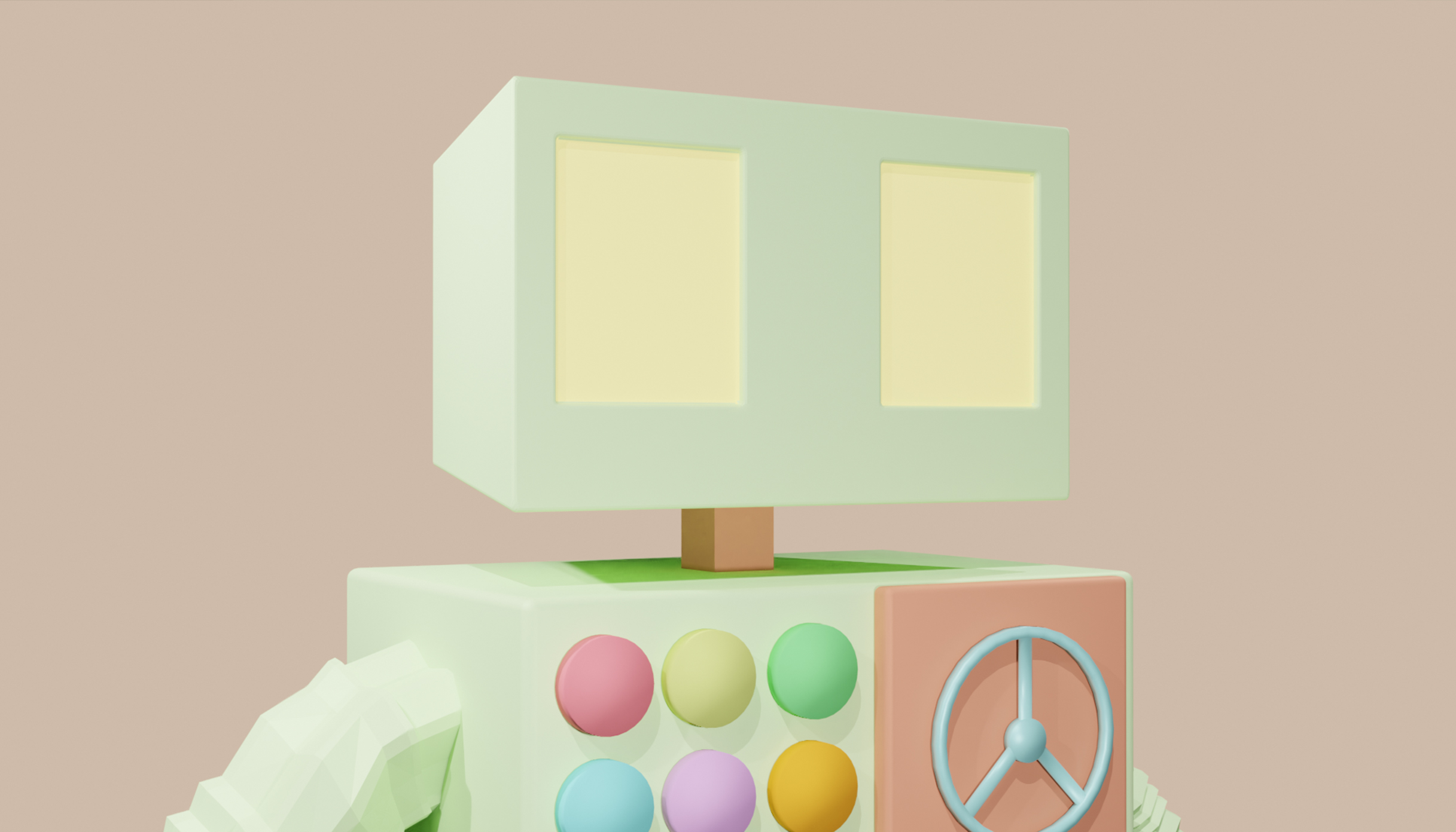
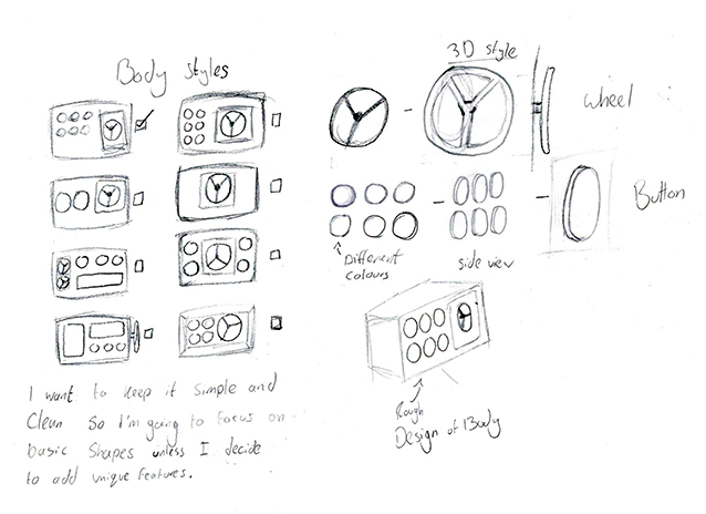
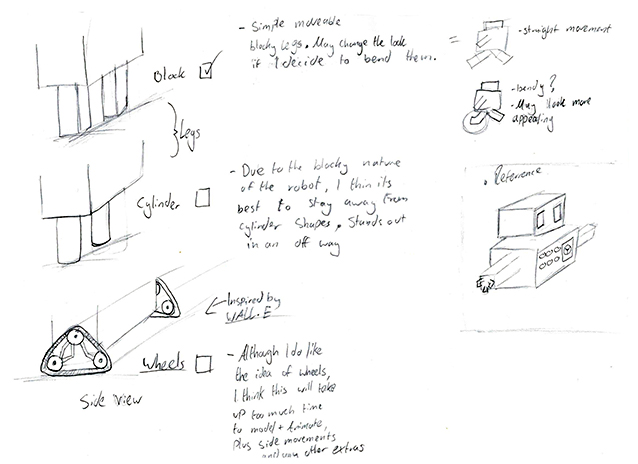
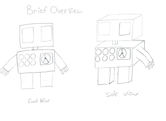
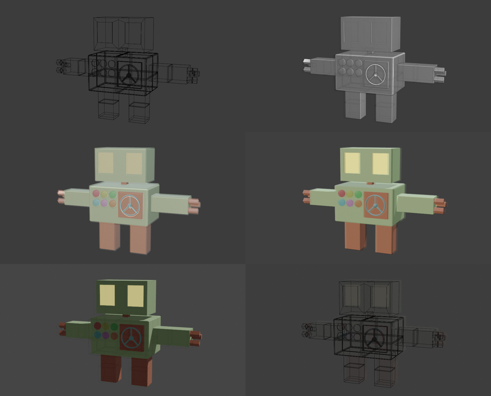
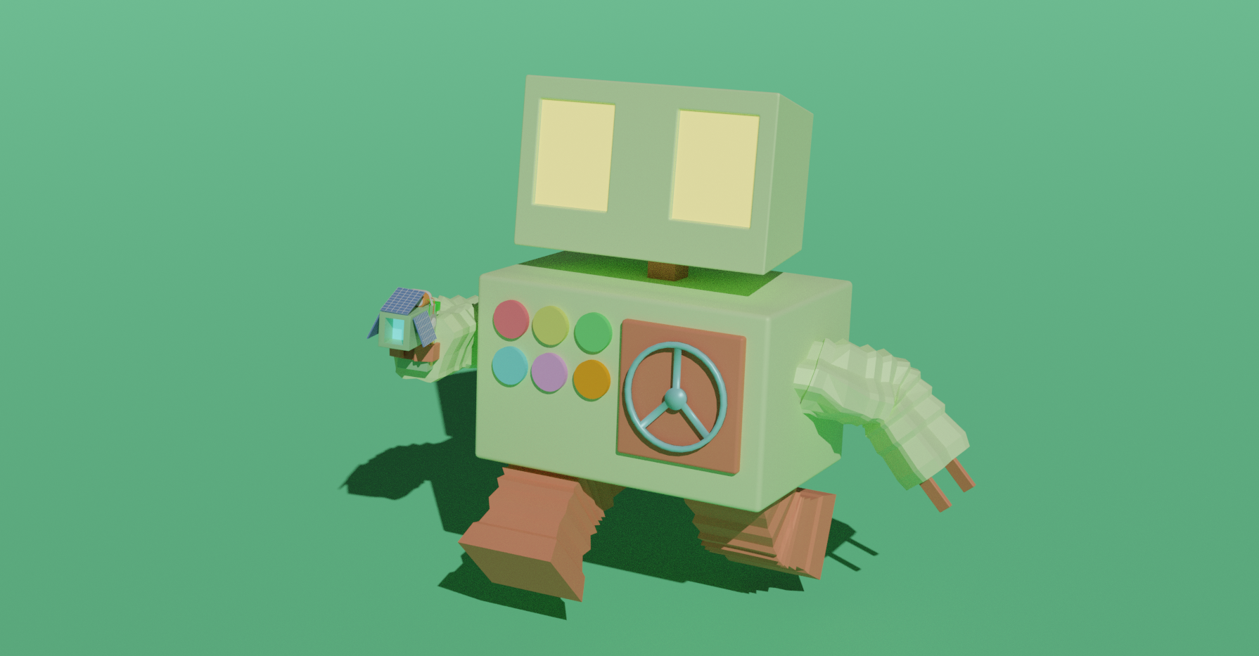
I think the overall assembly of my robot works pretty well, having closely followed my sketches to create my robot in the way I intended. I wanted to show the robot from wireframe to the rendered version to show how the general structure was built, showing the focus on the cuboid form whilst displaying how the eyes have a glow to them.
The buttons on the robot are mainly just for display, but are meant to signify that the robot has some kind of functionality that is triggerable. Finally, the behind the wheel on the body was to signify a storage area where something important would be kept inside, such as a power source, however I have kept it a mystery in hope to engage some type of enigma.
NS@2021
1.2.1
1.2.2
1.2 Key parts of assembly
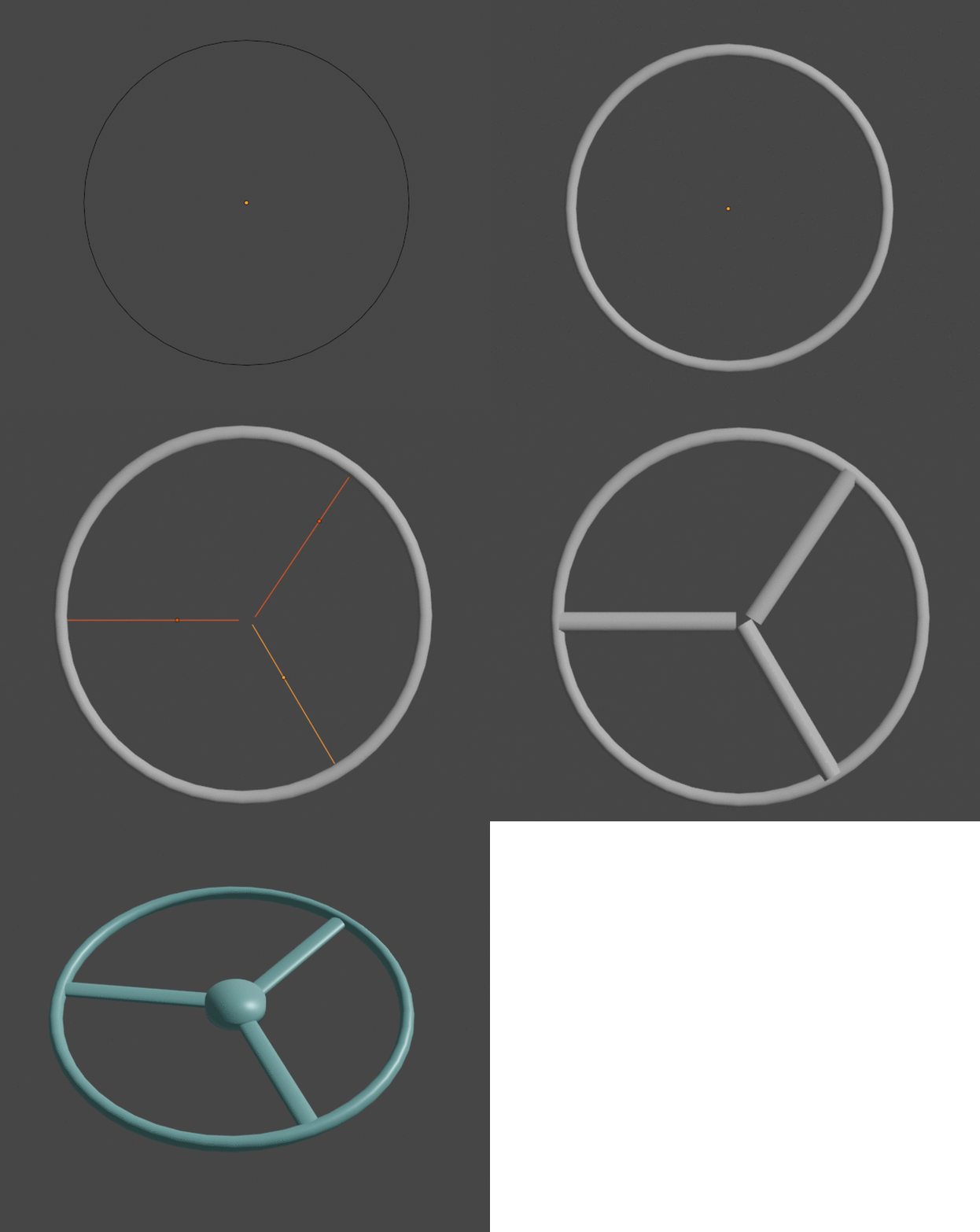
When constricting the wheel, I found a tool by navigating to the add menu Curve > circle. Navigating to Object Data Properties > Geometry > Bevel, I was able to increase the depth of the circle, creating a perfect connected tube (1.2.1). Later I used a similar tool Curve > Bezier, has the same functionality however this one is line that can be curved in any way. This allowed me to create the handles for the wheel, having symmetrical tubes that I was able to then flatten by transforming them into a mesh in Object > convert to > mesh (1.2.1).
Finishing off, I added a simple circle, filled it in, extruded it down and used the insert tool to create a new face and rescale it to a smaller size (1.2.2).
NS@2021
1.2.3
1.2.4
The Head
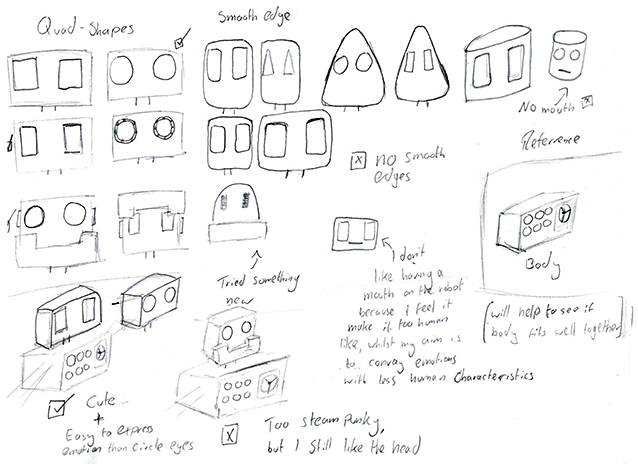
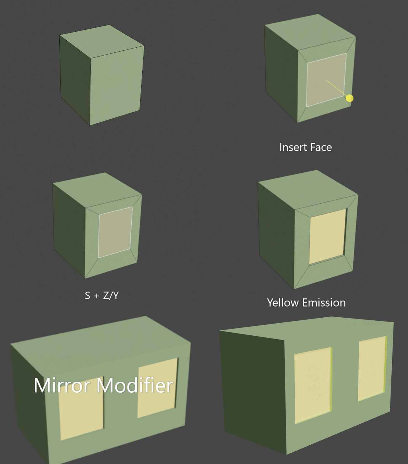
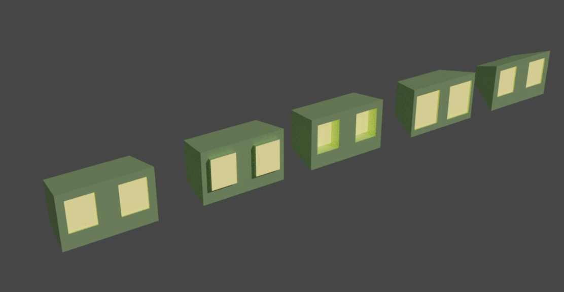
When creating the head (1.2.3), I found that the mirror modifier helped out a lot during the making of the robot. I’ll use the creation of the robot’s head as an example. You can see that I originally worked on half of the head, setting it up until I was satisfied. From then onwards, I added a mirror modifier in the opposing axis. This allowed me to then make any final changes whilst still working on one half. After I finished the head, I made some variations (1.2.4) to see which one fits best, changing the size and depth of the eyes whilst changing the shape of the body.
This process has helped me throughout the creation of my robot since I was able to use the mirror modifier with both the arms and legs, not having to worry about incorrect positioning. And even if the mirror modifier is applied, I can always separate the two objects by pressing alt + p.
NS@2021
1.3.2
1.3.3
1.3 Rigging & Armature
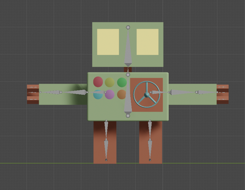
I began the rigging process to create an armature in a T pose for when I apply ‘automatic weights’. This feature calculates how much influence a particular bone would have on vertices based on the distance from those vertices to a particular bone. If this was done while my robot had their arms down, it will cause the arm bones to have some influence on the body.
I started with body bone and used it as the centre of the model. When configurating the armature, it’s important name each bone in an industry standard and label what side of body they are located. This will make armature configuration much easier as you can later symmetrize the rig with Blender changing the .L to .R. However, this is also very important when importing into Unity as the program will be able to locate each bone by name.
1.3.1
NS@2021
Key Notes:
- T pose is best for ‘Automatic Weights’ as it will be more precise and not overlap weights.
- Rename bones to industry standard names as it will help to make Unity understand the armature better.
1.4.1
1.4.2
1.4 Arm Development
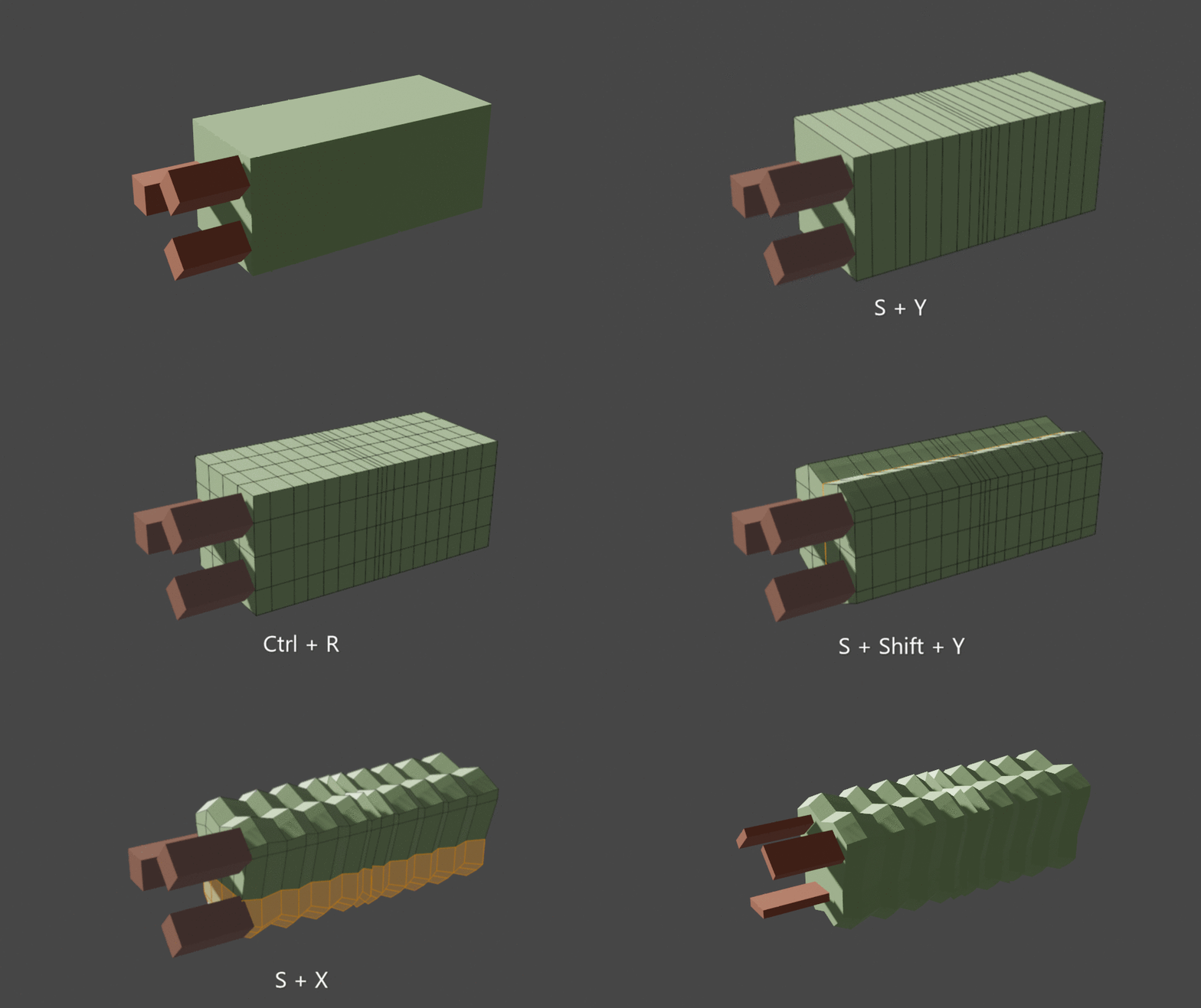
When thinking about how to make the arm have an understandable bend, I came up with a unique design (1.4.1). I used the loop cut tool to help me create various amount of segments on each axis of the arm. However, I used the keyboard short cut Ctrl + R to allow me to scroll wheel the amount of segments. The rest of the process mainly consisted of rearranging the segments and resizing them using various axis. When testing out the arm in pose mode I was very satisfied with the outcome (1.4.2).
I started with body bone and used it as the centre of the model. When configuring the armature, it’s important name each bone in an industry standard and label what side of body they are located. This will make armature configuration much easier as you can later symmetrize the rig with Blender changing the .L to .R. However, this is also very important when importing into Unity as the program will be able to locate each bone by name.
NS@2021
Key Notes:
- When using the Loop Cut Tool, using the keyboard shortcut 'Ctrl + R' will allow you to use your scroll wheel to increase or decrease the amount of segments made.
1.4.3
1.4.4
Fingers Adjustment
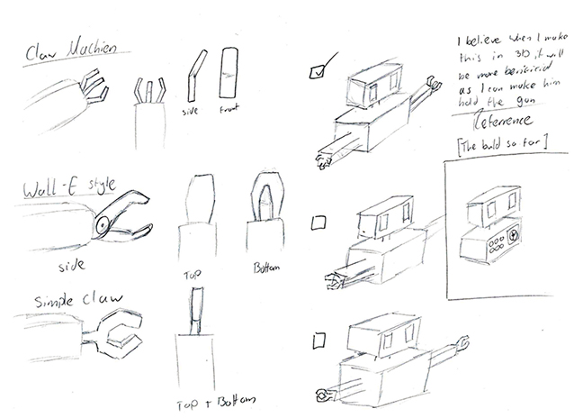
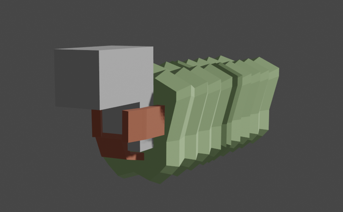
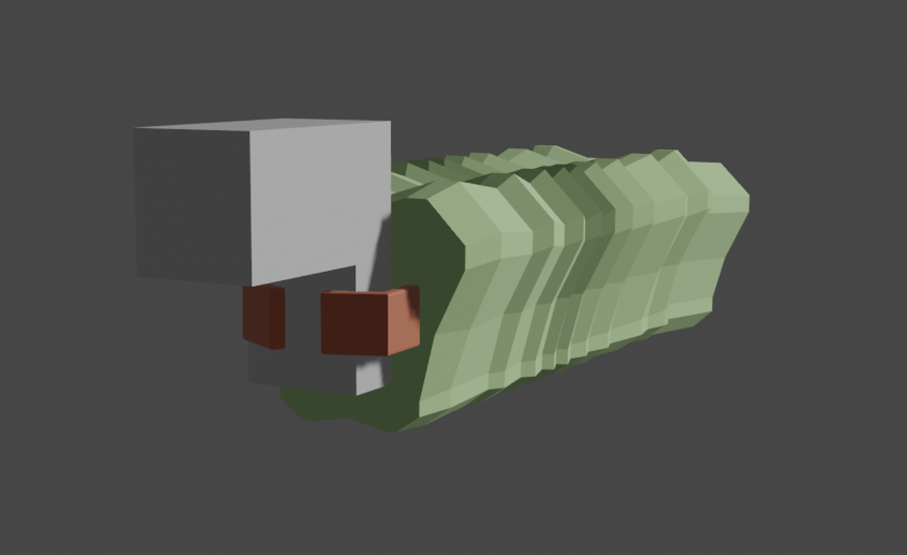
When I finished the arm upgrade, I wanted to make a quick test on how will the robot hold the gun, as I was having second thoughts on how will the 3 fingers function. I created a simple gun model that resembled my initial design to simulate how the robot will hold it (1.4.3). I had found that the 3rd finger didn’t really have much use and generally looked a bit off. My initial thoughout was to make it a holder, a place for the gun to sit on. However, I found that removing the 3rd finger made visual and functionality improvements, having the theory that the robot can bend their fingers more to trigger the shoot button (1.4.4).
NS@2021
Key Notes:
- When using the Loop Cut Tool, using the keyboard shortcut 'Ctrl + R' will allow you to use your scroll wheel to increase or decrease the amount of segments made.
1.5.1
1.5.2
1.5 Legs Development
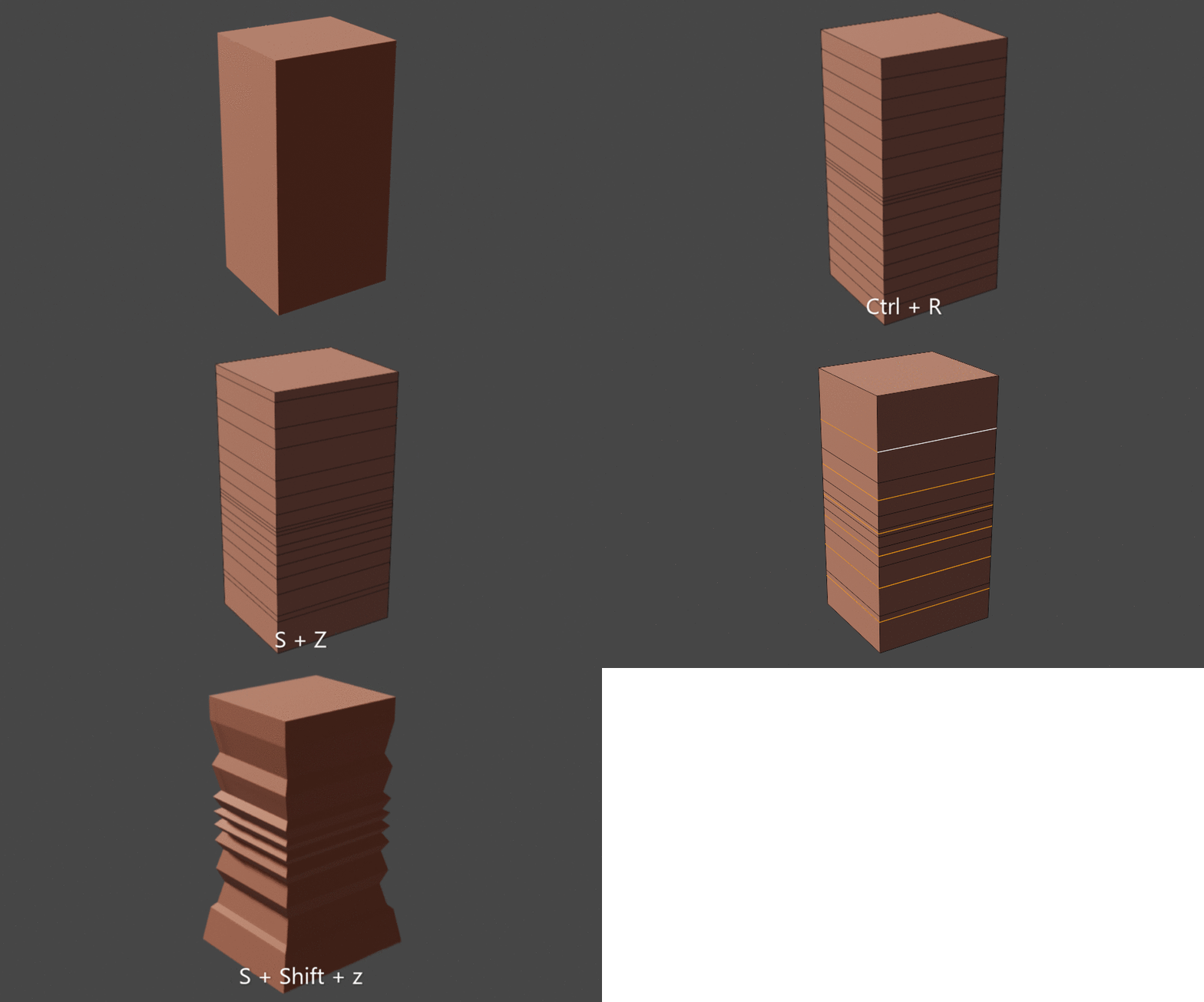
For the leg, I followed the same process as the arm. Using the Bevel keyboard shortcut Ctrl + R, I created a similar number of segments, rearranged then positioning and resized every other segment using S + Shift + Z which resizes in both X & Y (1.5.1). I was satisfied with the result and how the leg bends (1.5.2), keeping the same theme as the arms. This form can also allow me to create interesting mechanics in the future, such as springing legs that can add a cartoon style.
NS@2021
1.6.1
1.6.2
1.6.3
1.6 Kinematics
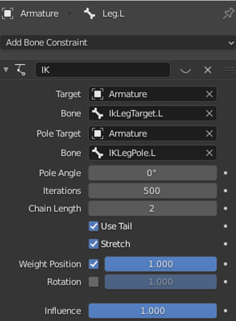
Kinematics were very useful when as you can move a single bone to move an entire section, such as a whole arm or leg. When you have your bone selected, I navigated to Bone Constraint Properties > Add Bone Constraint > Inverse kinematics, adding a constraint that allowed me to link everything up (1.6.1) . I selected the Chain length to 2 since there are 2 bones connected to the bone I want to move.
When creating a kinematic you need to have a minimum of 2 extra bones, a target and a pole. The pole target is a secondary target for a bone with an IK constraint. The target bone is where the chain of bones is trying to get to, and the second target (pole target in constraints), is where the chain bends to get to this target.
I cleared the parent of the targets using the keyboard shortcut Alt + p, separating the pole and target from the armature. To prevent these bones from deforming the mesh, since they’re for controlling use, I navigated to Bone properties > Deform and unselect deform.
The outcome of this process helped me to freely move the inter leg (1.6.2) and arm (1.6.3) using 1 extra bone as the controller. The movements are both very smooth and will work perfectly when animating.
Key Notes:
- Adding a bone constraint on your selected bone allows you to set up an IK rig and make it move with other bones!
NS@2021
1.7.1
1.7 Vertex Groups & Weight Painting
Vertex Groups
I started by selecting a piece of the body that I want to configure, in this case the right arm. With the right arm selected, I navigated to Object Data Properties (1.7.1). This is where the Vertex Groups are located, a list of all the bones that are able to move your selected object.
I didn’t want any unrelated bones that could have the potential to move my right arm. This can be easily sorted by locking all the bones you require, move them to the top and remove all the bones you don’t need.
I followed this method for all the Robot’s body parts, later making the weight painting process easier as I will also now instantly see what bones I need to weight paint, whilst not having to worry about some incorrect automatic weights.

1.7.1
1.7.2
Weight Painting
Weight paint allows me to determine how much movement a bone has. This includes the determining a focus of an area (head, arms, legs) or smoother movement (such as bends).
I used the gradient tool instead of a brush because it made the process more time efficient, and due to me not needing to paint in certain areas of each mesh to fix any weight errors (fixed by removing vertex groups) (1.7). I used max strength and weight to make sure that the area I was working on was filled to the point I wanted it to be.
Weight paining is determined by colours, red meaning that the bone has full control of that location while the blue has none. Yellow has 75% control of the location and green having 50%. Yellow and green are mainly used for a smooth transition from red to blue, so they need to be in the mid point of the area you want to have smooth movement.
NS@2021
Key Notes:
- To see your bones while weight painting, select your armature, navigate to Object Data Properties > Viewport Display and tick the In Front box!
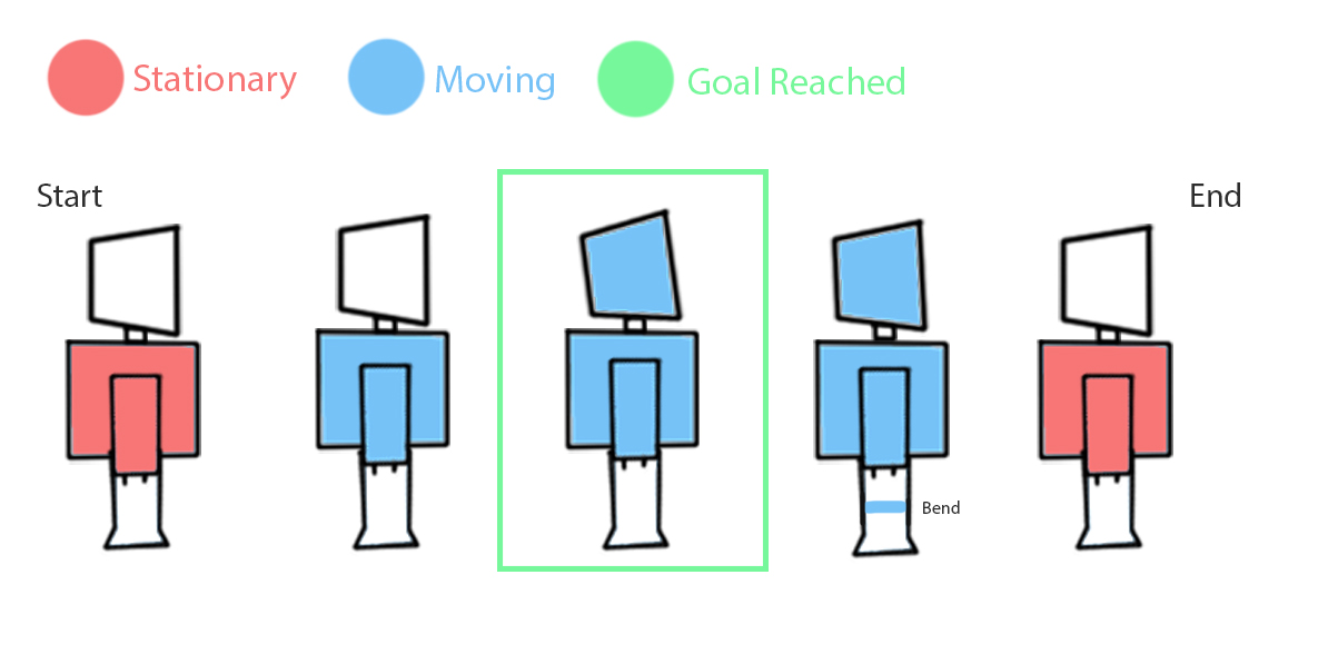
1.8.1
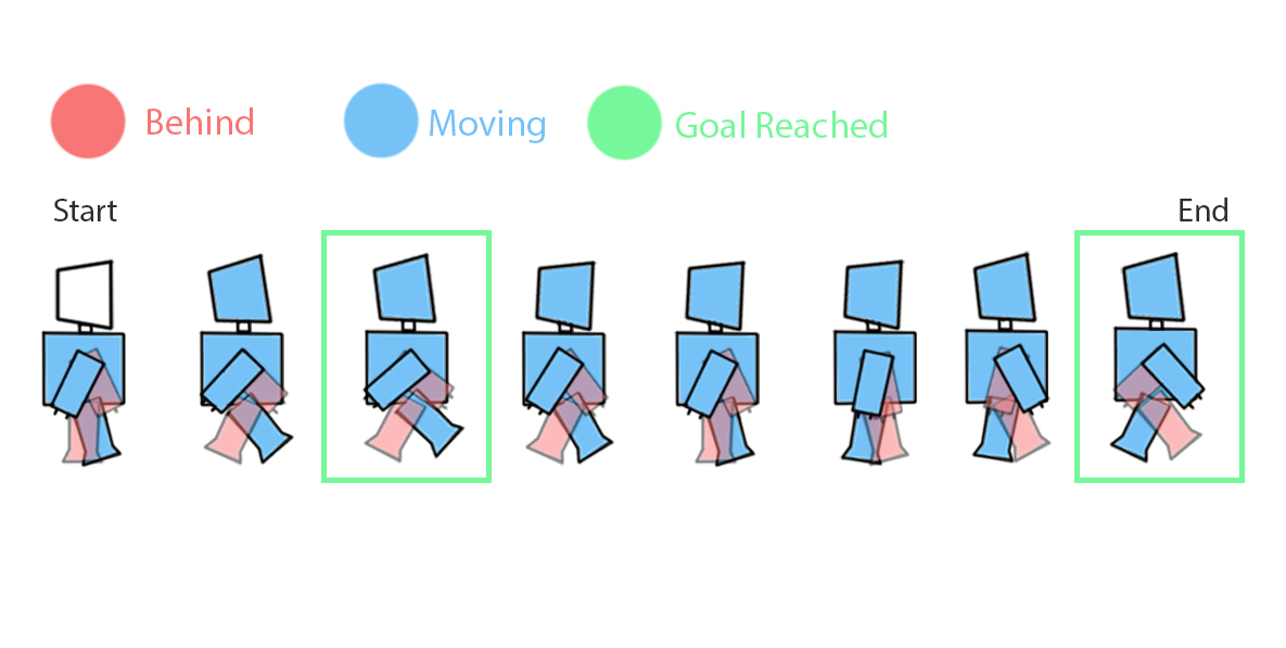
1.8.2
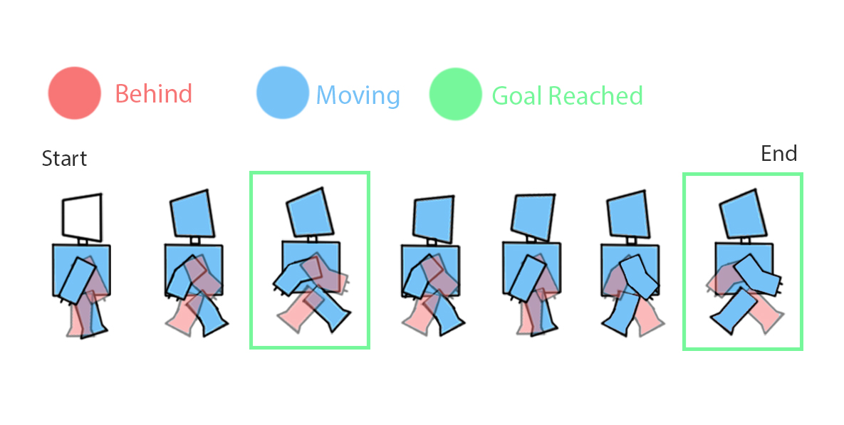
1.8.3
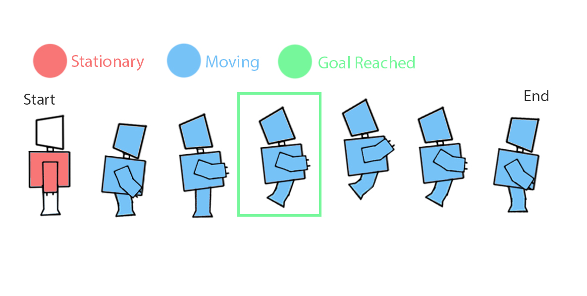
1.8.4
1.8 Robot Animations
Planning
When planning for my robot animations, I drew a few frames in Photoshop of what is supposed to move and how. I did this for all 4 of my animations: Idle (1.8.1), walking (1.8.2), running (1.8.3) and jumping (1.8.4). These were the key animations I needed for the general functionality of the robot.
Each drawing has its own colour code that determines what action is being taken placed. The green box was drawn to display when the robot reaches their first goal of the animation, meaning it will begin to trigger a different sequence.
NS@2021
Key Notes:
- It's always important to plan out an animation when it requires lots of movement as it can help you know what step to take next!
- It may be useful to create a color code key as it can help you know what part you need to focus on!
Understanding Key Frames
1.8.5
1.8.6
1.8.7
A Keyframe is simply a marker of time which stores the value of a property. In other words, it’s a time stamp of the current position of your armature/specific bone. This is what allowed me to animate my robot, using my plan to help me move each bone in the correct. This resulted in blender moving the bone from point A to point B (1.8.6) (1.8.7).
This process has helped me throughout the creation of my robot since I was able to use the mirror modifier with both the arms and legs, not having to worry about incorrect positioning. And even if the mirror modifier is applied, I can always separate the two objects by pressing alt + p.
When adding a keyframe, I always selected Location, Rotation & Scale option. This means that the keyframe will remember the exact position.
To adjust the speed, I simply just extended a keyframe a few frames further or shorter, meaning the speed of the timeline traveling from point A to point B will alter. Finally, in the Action Editor I compiled all the animations into their own animations (1.8.8). This allows me to export my robot into Unity with each animation in its own package.
NS@2021
Rendered Animations
1.9.1
1.9.2
1.9.3
1.9 Solar Powered Gun
Sketches
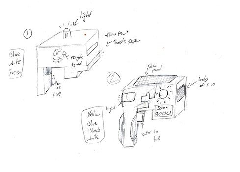
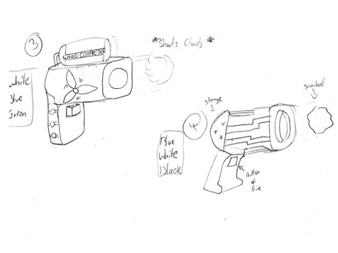
I started to draw out some ideas for a solar powered gun whilst following the basic gun shape. I came up with a total of 4 concepts, labelling each one with its own colour code. I also experimented with different functionality on each gun, seeing what works and what doesn’t.
The one design I was most fond of was a gun that had extendable solar panels(1.9.1) (2), meaning the user will no longer need to reload. I would hope that by adding this feature on the gun will educate the players on the Importance and usefulness of reusable solar energy.
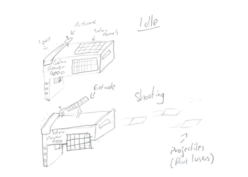
I also did a rough sketch on how the gun will shoot and what actions will happen during the process (1.9.3).
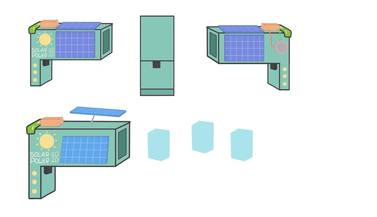
Further developing the gun, I drew the concept in Photoshop. I drew each side of the gun and applied colour to have an idea of how the outcome will look (1.9.4).
1.9.4
NS@2021
1.10.1

1.10.2
1.10 Modeling
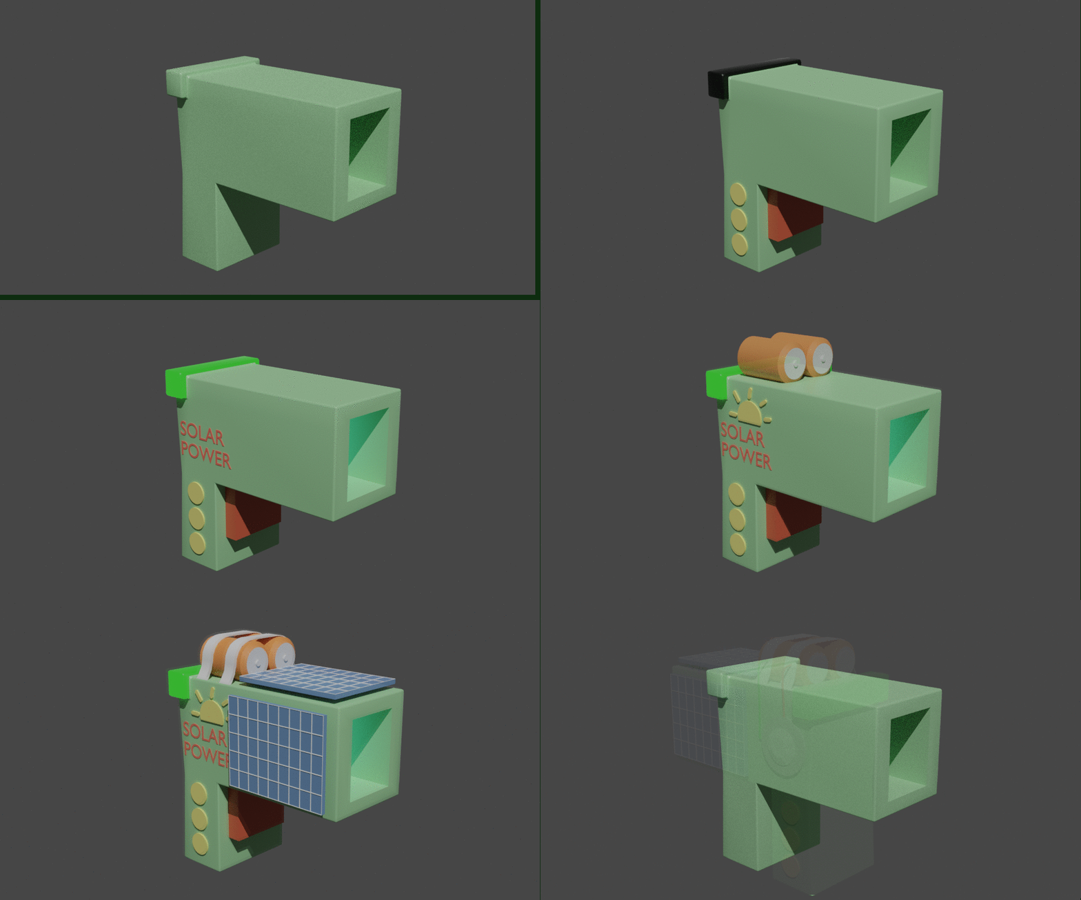
I made the body by extruding a cube to a gun shape and added a Bevel Modifier to smoothen the edges. This was followed by the main button of fire and 3 circles for the decoration of the gun.
The back light of the gun was made by selecting a small section and increasing the scale, whilst keeping it in the smooth shape due to the bevel modifier. Navigating to the Shading Tab, I increased the transmission and decreased the roughness, giving it a shiny plastic look while emitting light(1.10.1).
To create the sun logo (1.10.2), Illustrator was the way go due to it being a vector graphic program. Vector graphics are points, lines and curves that are based on mathematical formulas, meaning it can never become raster (pixelated). After I drew the sun logo, I exported the file in an SVG format (Scalable Vector Graphics), imported it into blender and converted into a mesh by Object > Convert to > Mesh. However, the mesh was filled with too many vertices that were not needed. mode and deleting using Limited Dissolve, reducing the detail on planer faces and linear edges with an adjustable angle threshold.
The text “Solar Power” was done using the add menu in blender Shift + A > text, meaning I could simply type it out. I changed the text into a mesh and extruded to add some depth, making it 3D. (1.10.3)
Finishing the unsustainable look of the gun, I added 2 big batteries, followed by a metal holder. This will indicate that this gun can only do so much until it runs out of power. To now make the batteries look sustainable, I added 2 wires that connects to the gun, using the Bevier to position and change the depth.
NS@2021
1.10.4
Solar Panel
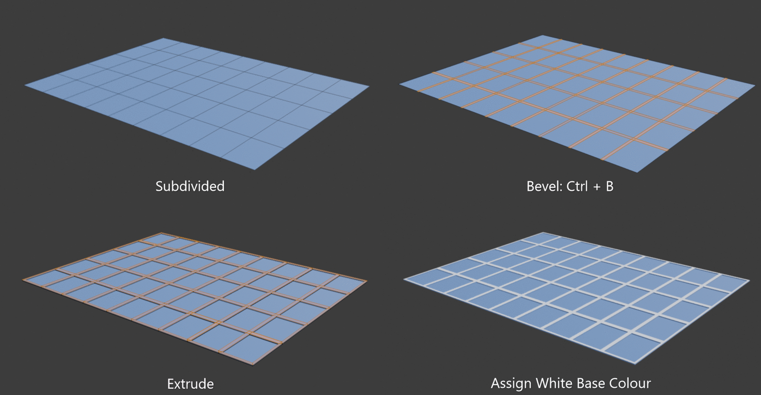
The making of the solar panels (1.10.4) was a simple method but quite efficient. I started with a plane and subdividedit in to section. I then selected all the edges and used the keyboard short cut Ctrl + B to make the bevel instantly focus on my selection. The bevel tool was useful as it made equal space surrounding each edge, meaning I could then select all the lined faced and extrude them, making a 3D grid. Finally, whilst I have everything selected, I assigned a white base colour.
1.11.1
1.11 Animating
Using the skills I learnt when animating the gun, the process of adding bones and setting up the keyframes was much faster. I started by making the solar panels extend (1.11.1). This was done by adding 2 bones for each solar panel set, since using one bone will deform the solar panel and the pole its attached to. One bone focused on extruding the panel, whilst the other focused on the rotation (1.11.1).
When the rotation was completed, I added an extra bone for the body of the gun, allowing me to create an animation of the gun shooting, whilst displaying how the solar panels extension will work (1.11.2).
1.11.2
1.9.11
Display in Hand
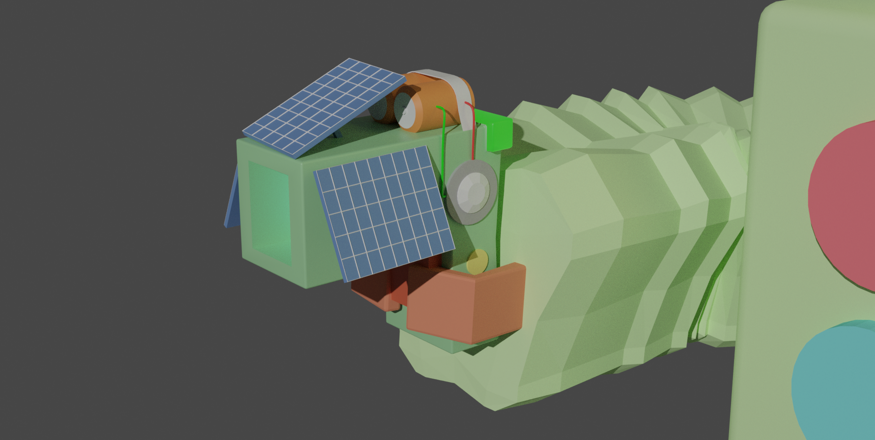
As the gun was finished, I did a test on how it will fit the robot’s hand. I was very pleased on how it visually looked and glad that the functionality of the button press can still be done. Although it seems a bit too small when holding, the intention was to make the robots arm point forwards when shooting, making sure the player can see it.
Gun Animation
Rendered Result
Overall, I’m proud that I got as far as I did in this project, learning completely new things and pushing me past my limits of what I thought I can do. I feel more confident in my work and think I can have a lot to offer as a team member. I’ve learnt a unique sketch design process such as building a concept in blocks. I’ve learnt more Blender keyboard short cuts and general short cuts to help me speed up my working time. And finally, I’ve learnt some fundamental features of unity such as coding and how to navigate thoughout the program.