Virtual Cities | Visualize the City of Winchester | 1700s
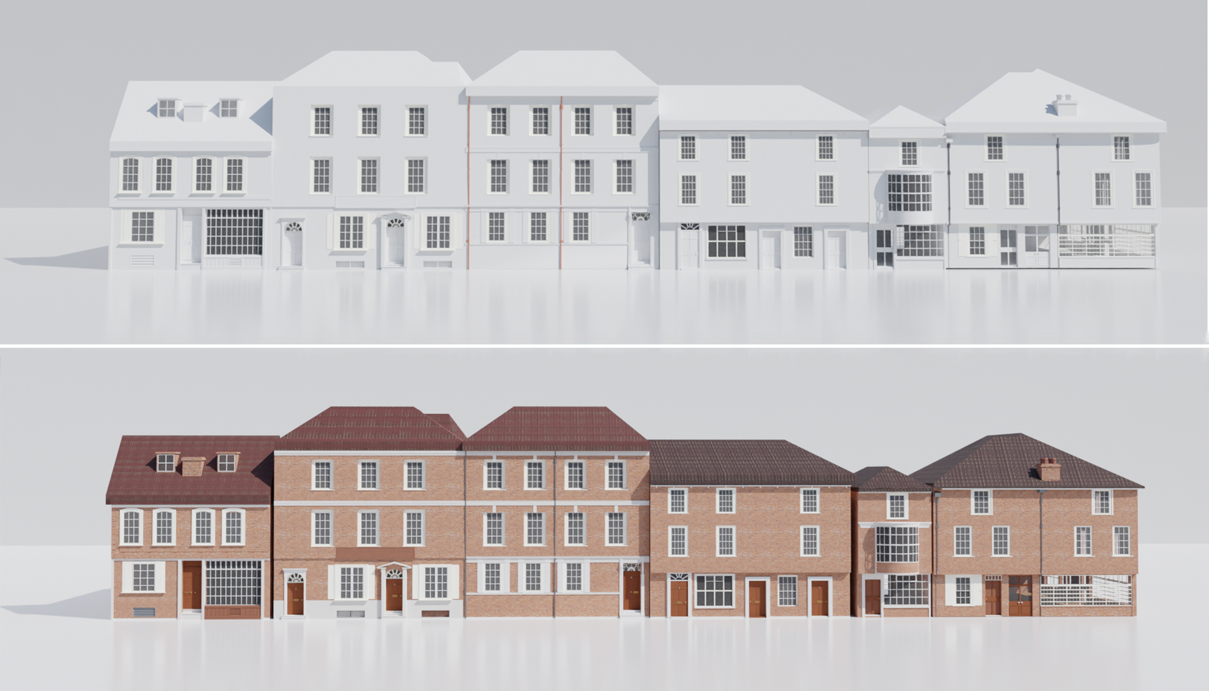
Brief
Reproduce historic landmark buildings in 3D and take them into the Unreal Game Engine to create a realistic version of Jane Austen’s Winchester (1775 - 1817).
Goal
Recreate College Street within the 1700s, a total of 6 buildings with great detail to display Jane Austen's Winchester.
Role in Project
Team Leader
3D Artist
Software
![]() Blender 2.93
Blender 2.93
![]() Quixel Mixer
Quixel Mixer
![]() Autodesk Revit
Autodesk Revit
Prep
1.0 Introduction to Project
1.1 Who was Jane Austen?
1.2 Choosing the buildings
1.3 Property Archive Research
Building #1 | Revit
1.4 Visual Measuring
1.5 Visual Measurements
1.6 Walls & Floors
1.7 Ceiling Creation
1.8 Offset
1.9 Creating the roof
2.0 Creating Windows
2.1 Adding Door Placeholders
2.2 Window Alignment
2.3 Building Results & Exports
Building #2 | Revit
2.5 Building #2
Building #3 | Revit
2.5 Building #3
2.6 Bug Fixing
2.7 Modifying Sub Elements
Building #4 | Revit
2.8 Building #4
Building #5 | Revit
2.9 Building #5
Building #6 | Revit
3.0 Building #6
Blocking out College Street
3.1 Block out College Street
Building #1 | Blender
3.2 Building #1
3.3 Door, Window & Details
3.4 Pipes & Chimney
3.5 Final Results
Building #2 | Blender
3.6 Building #2
Building #3 | Blender
3.7 Building #3
Building #4 | Blender
3.8 Building #3
Building #5 | Blender
3.9 Building #5
Building #6 | Blender
4.0 Building #6
White Blocked Street Render
4.1 White Blocked Street Render
Mixer x Blender
4.2 Brick Material
4.3 Principled Texture Setup
4.4 UV and Texture fixed
4.5 Bricked + Roof Adjustment
4.6 Roof Tiles Texture
4.7 Applying Roof Tiles Texture
4.8 Window Readjustment
4.9 Photo-Realitic Materials
5.0 Conclusion
1.0 Introduction to Project | Client : Deborah Wilson
Deborah Wilson is the Owner of The Talking Walls UK Ltd, currently in development for the heritage
industry. This is a multimedia, visually rich educative application for users to explore their
environment through the ages on a small screen device. The Talking Walls® is a wireless, multi-
platform, multimedia application designed for users to explore and navigate where they are visiting
via a mobile/handheld device. This is a great way to see how history has changed over time, exploring
specific time-slices of space, defined by the architectural changes to the property.
Deborah teaches on the Digital Media undergraduate and postgraduate programs and is currently the
Programme Leader for the Digital Media programs at the University. Being an owner of The Talking Walls
UK, Deborah has asked us to assist in her project, recreating Winchester virtually.
We had assembled a team and had decided on what structures to build. Although this project was team-focused,
we all agreed to work on our structures in the way we want to build them, and later add all structures within
the existing Unreal Engine project.
1.1 Who was Jane Austen?
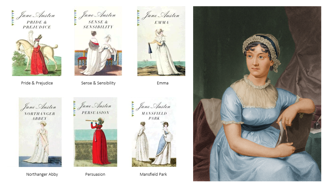
Born in 1775 in a small village in Hampshire, Jane Austen was an English
novelist known primarily for her six major novels, exploring the dependence
of women on marriage in the pursuit of favorable social standing and economic security.
By choosing not to marry and writing novels instead, Austen challenged the notion that
unmarried women could not support themselves. Her novels were her chosen weapon in the struggle
to reform humanity, writing a total of 6 complete novels.
1.2 Choosing the buildings | College Street
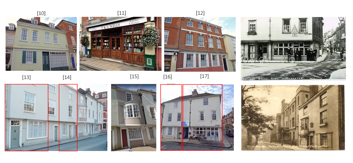
Out of the list provided to me, I decided to re-construct an entire street, a total of 6
buildings that stretch out to Jane Austen’s house. College street is significant because
this is where Jane Austen moved for medical treatment, her home being number 10. Unfortunately,
this building had been already made, so I created all the buildings that led up to it.
I had also found some old photos of college street, in hopes of helping me visualize how it
looked back then. Unfortunately, there were no photos of the 1700s that displayed College Street,
so these few photos were all I had to go with.
1.3 Property Archive Research | Winchester City Council
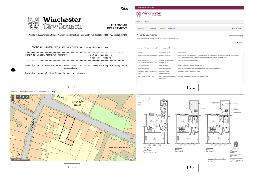
I tried investigating further into the property archives that Winchester city council has provided, but not much was found. Although the buildings im creating are listed in the archives, not much information is given in terms of the building visuals. I’ve looked at old documents [1.3.1], constraints [1.3.2], and the map provided on their website [1.3.3]. I did however manage to find a floor plan for building 12 [1.3.4], gaining a better understanding of the measurements and what is located where. Unfortunately, this was the only floor plan I was able to find, so this led me to my next approach.
1.4 Visual Measuring | Building #1
With the game mechanics decided, we needed to be set an art style. Found a TV series known as Adventure Time (1.4.1), a very popular cartoon adventure series that also have a similar demographic to our target audience. The show has a unique and consistent cartoon art style (1.4.2), to which we felt would work very well with our concept!
1.5 Visual Measurements | Revit
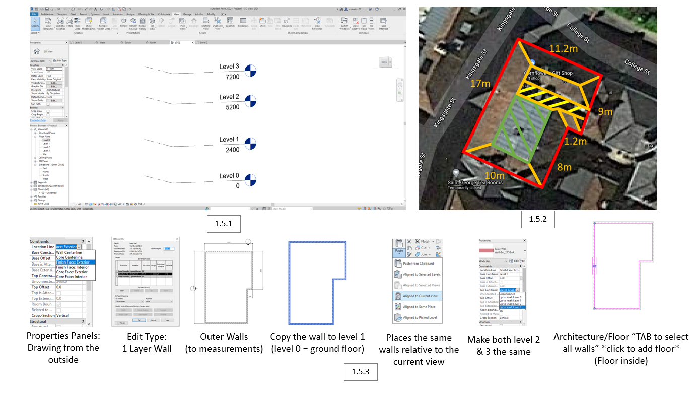
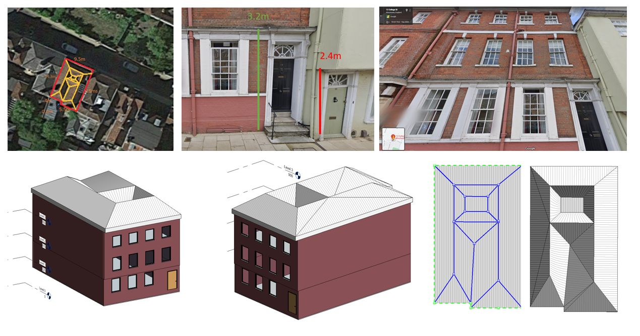
Following my way of measuring, I moved to Google Maps to get started on measuring
the outer walls of the building. I used various colours to separate various areas
[1.5.2]; red being the outer walls, orange for the roof edges, green for the top
flat surface, and yellow for the lower flat surface. However, later down my development, I found that the green area was not flat at all, more like a sheet of a metal layer on top in a certain way.
With the measurements done, I began my adventure with Autodesk Revit, an industry-standard
architectural-focused program, very useful in this project. I started by creating the 3 floors,
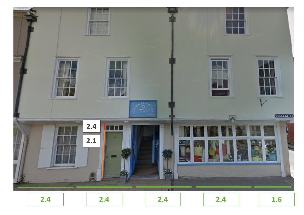
using my measurements from the door to assist. With the first bottom to the first floor being
2.4 meters [1.5.1], the building looks evenly spaced out, allowing me to conclude the rest of the measurements for the 3 floors
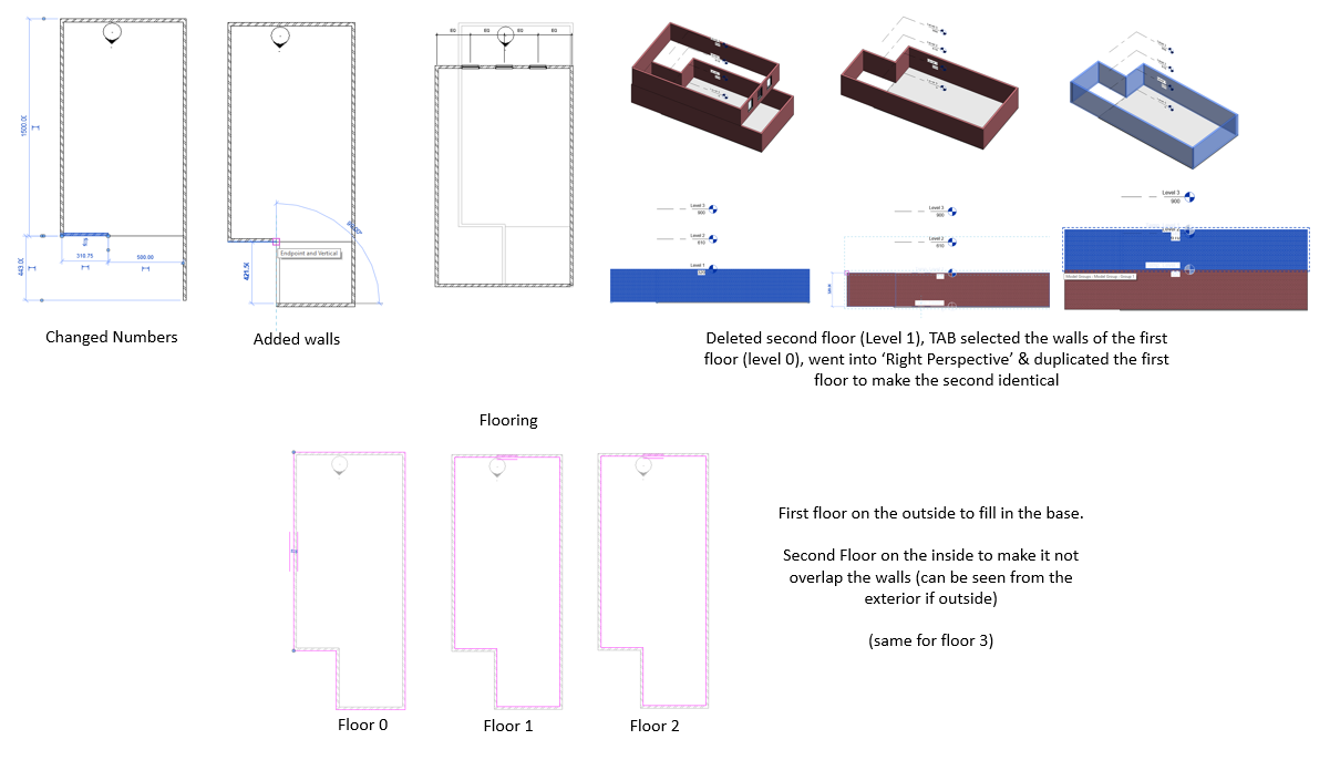
I’ve listed a step-by-step route of how I created my first-floor plan [1.5.3], using it to make my 3 floors with the basic walls. [1.5.1].
1.6 Walls & Floors | Revit
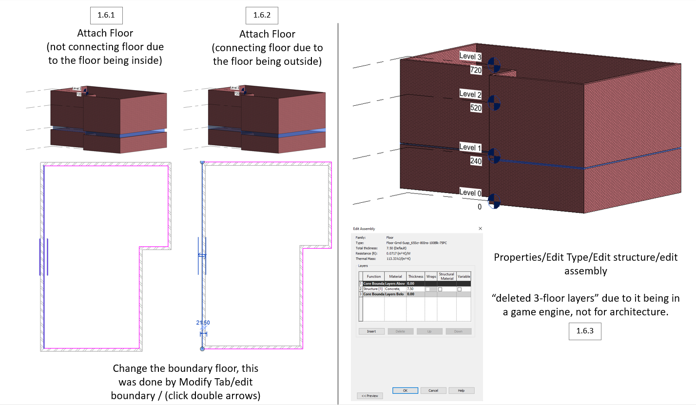
Further editing the floor, I found that you were able to change the boundary of the floor, making it attached (inside) [1.6.1] or not (outside) [1.6.2]. This was very useful to know as this can make an impact visually when editing later in Blender, having faces peeking through the walls. This meant I made the 2nd and 3rd floor inside, and the bottom on the outside, as the bottom needed a base.
1.7 Ceiling Creation | Revit
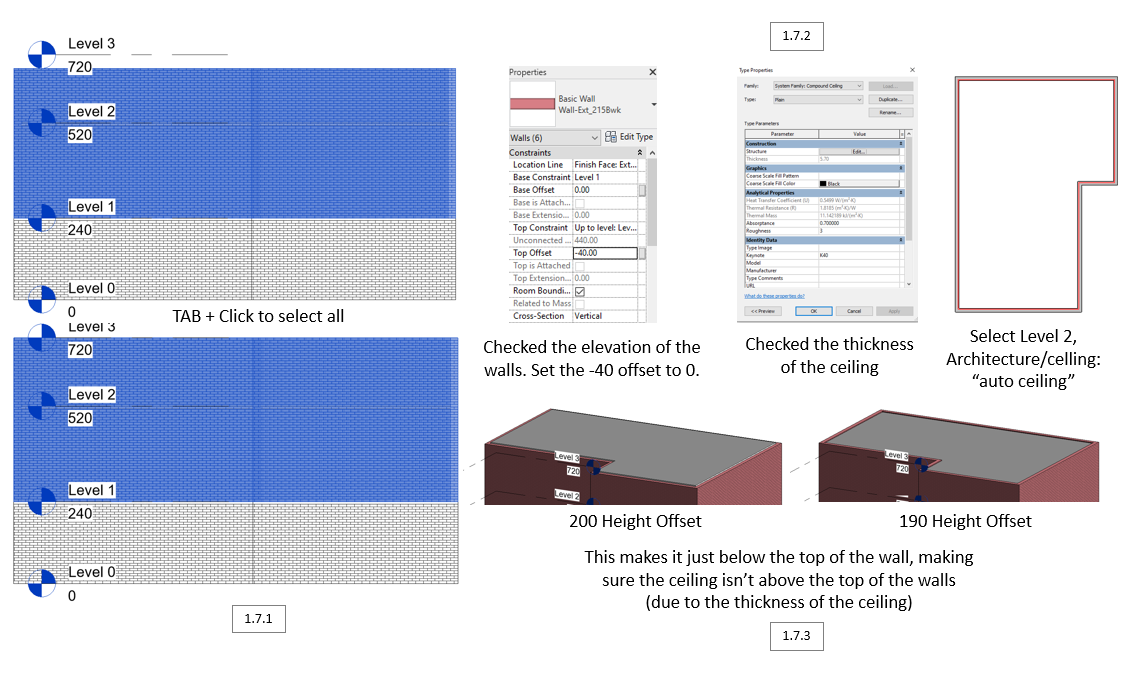
To create the ceiling, I started by TAB selecting the walls [1.7.1], later setting the offset from -40 to 0 [1.7.2],
making sure it’ll stay within the boundary of the walls. Checked the thickness of the ceiling [1.7.2] to make sure it’s
not too thick or too thin. I later found that that there was an automatic ceiling feature [1.7.2], which was helpful
for the other 2 ceilings. Finishing off, I set the height offset to 190 [1.7.3], making sure the ceiling wasn’t above the walls.
1.8 Offset | Revit
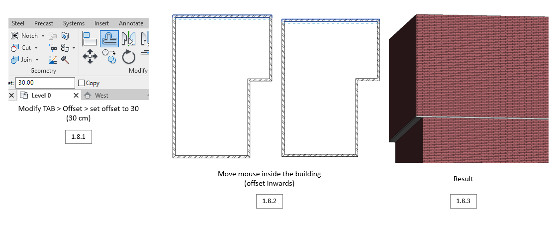
From the references of the buildings, I saw that the 2nd floor was offset from the first one. To make this, I modified the offset front wall by 30 cm [1.8.1], whilst making sure the inner wall was still facing the correct way [1.8.2], giving me a perfect offset [1.8.3].
1.9 Creating the roof | Revit
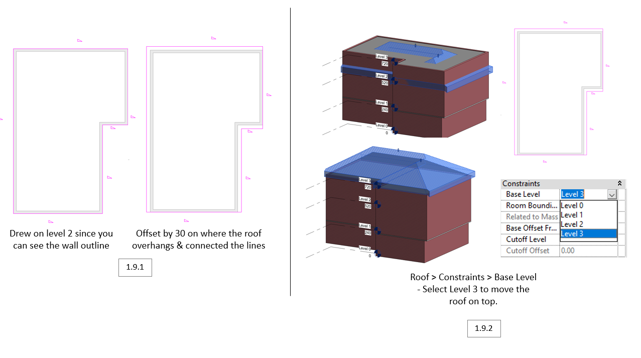
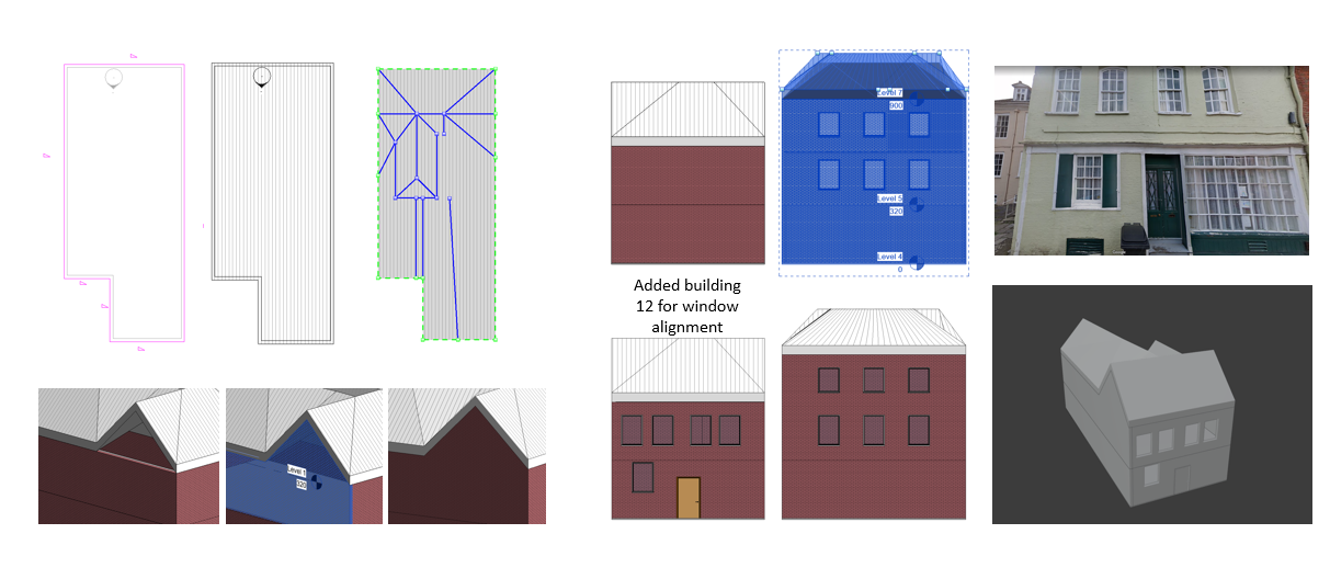
To create the roof, I first created an offset all-around on level 2 (since you can’t see level 3), making an overhang [1.9.1]. Redirecting to Roof > Constraints > Base Level, I selected level 3 on the constraints to move the roof to the 3rd floor [1.9.2].The roof was easier to make out of them all as it automatically calculates where the edges are.
2.0 Creating Windows | Revit
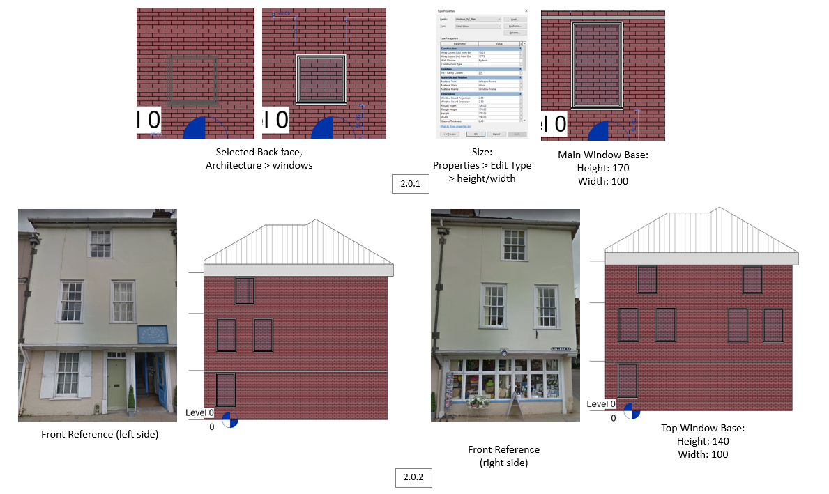
This is my process of making a window placeholder, keeping at only the basics of the building. This was done by adding a basic window and resizing it to look like reference image, aligning it accordingly [1.2.1] [1.2.2].
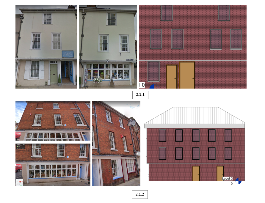
2.1 Adding Door Placeholders | Revit
The same process was done with the doors, simply adding them through the assets library and adjusting the size to fit the reference images. This was done for both the front [2.1.1] and the right side [2.1.2].
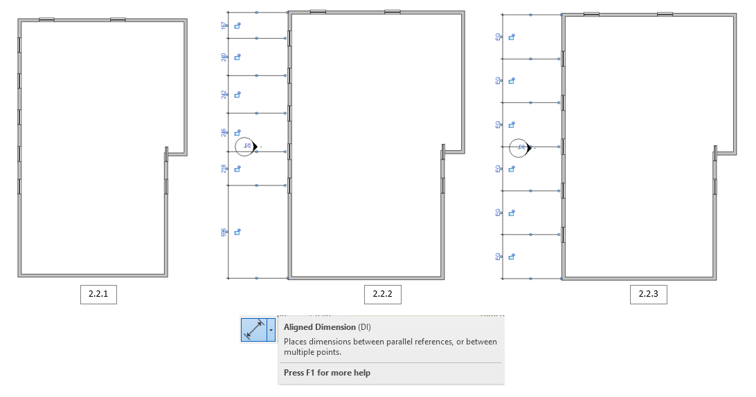
2.2 Window Alignment | Revit
This was mainly a quick tip I found quite useful later. By going into the top view [2.3.1], and selecting the aligned dimension tool [2.3.2], I was able to evenly space out the windows on each wall [2.3.3].
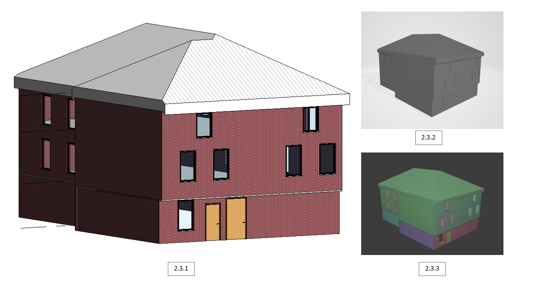
2.3 Building Results & Exports | Revit
After many hours of learning how to use Revit, I managed to create my first build [2.3.1]! The next steps were to export it to Blender. This was done by exporting as .FBX [2.3.2], and importing with the same file format into Blender [2.3.3].
2.4 Building #2 | Revit
After completing my first building, I was able to get the rest done much more smoothly, simply adjusting the sizes and repeating the process.
2.5 Building #3 | Revit
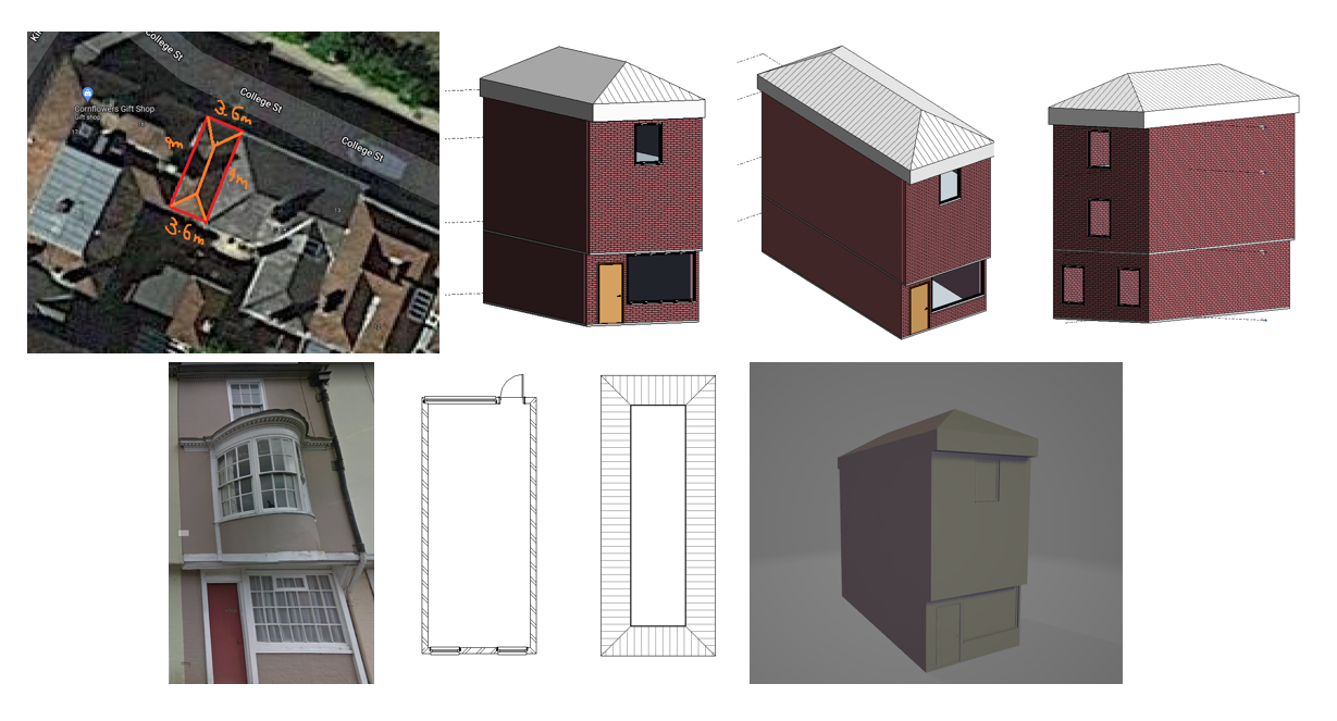
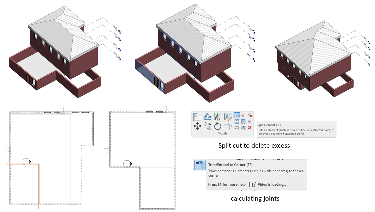
This is me showing one of the processes I went about when making more buildings,
using old buildings to make new ones. This method uses the split cut and calculating
joints tools, essentially, I overlapped the old building above a newly created layer
and extruded the faces to the correct position. This was followed by cutting off the
unnecessary walls. Although this method wasn’t the best option, it got the job done,
especially when I was new to the program.
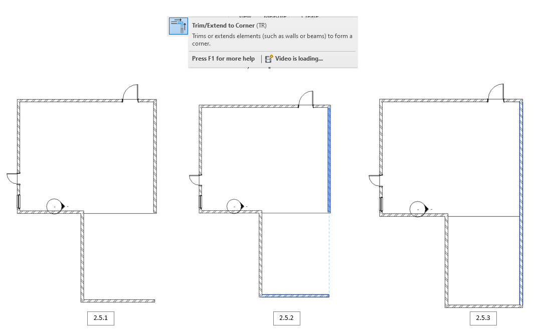
The second image shows how I reconnected the walls. When a gap was created [2.5.1],
I highlighted the 2 walls closest [2.5.2] and used the trim/extend to corner tool to connect the walls [2.5.3].
2.6 Bug Fixing | Revit
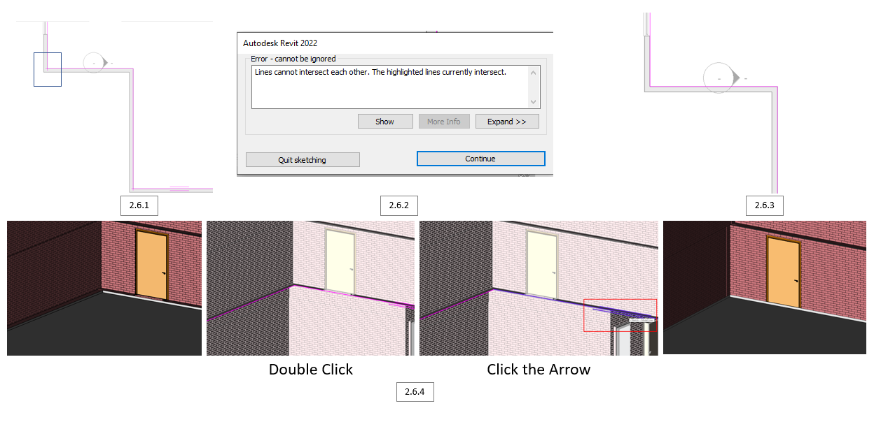
This was mainly a bug I wanted to show that was common when trying to offset. The issue was that lines intersected at the corners [2.6.1]. which gave this error [2.6.2]. This was fixed by selecting the floor and clicking a small arrow above [2.6.4], removing the intersection [2.6.3] and offsetting accordingly.
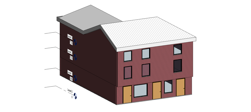
2.7 Modifying Sub Elements | Revit
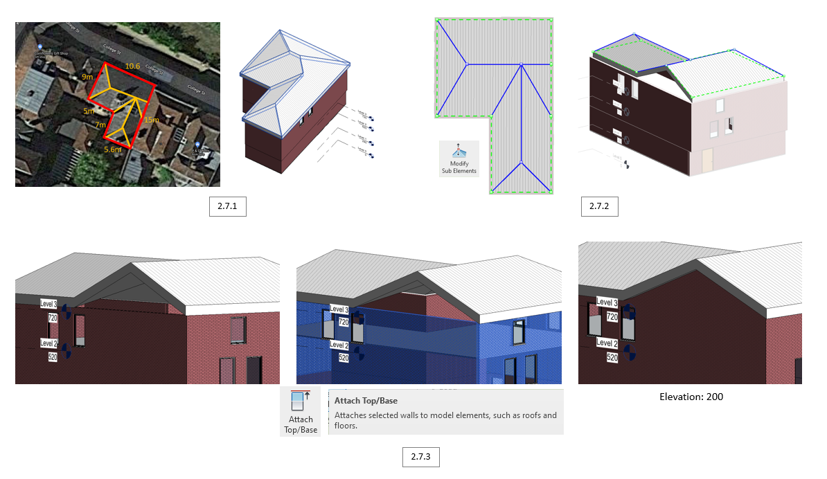
When creating the roof, it’s not always calculated to be the one I needed. Looking at the reference images vs what Revit calculated [2.7.1] you can see it’s not the exact same. I flattened the roof using Modify Sub Elements, allowing me to draw my own edge lines [2.7.2]. I later come across an issue where there as a triangular spacing. This was resolved by using the attach top/base tool, simply selecting the wall and roof using the tool and it connects [2.7.3]
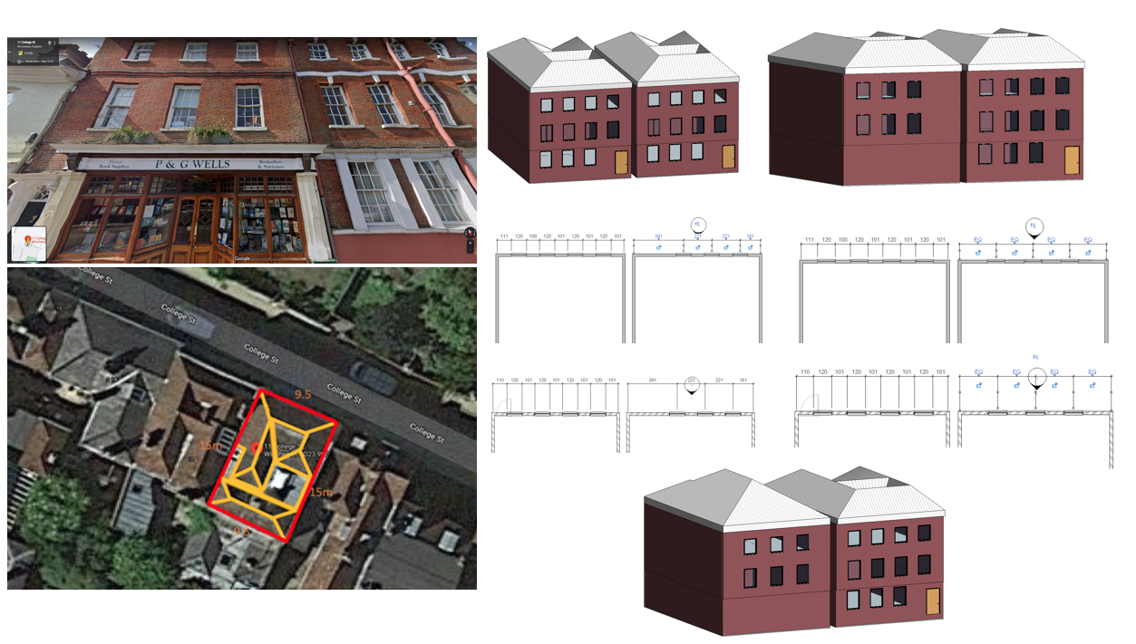
2.8 Building #4 | Revit
A summary of what I did for the 4th building, using the same techniques as done before.
2.9 Building #5 | Revit
A summary of what I did for the 5th building, using the same techniques as done before.
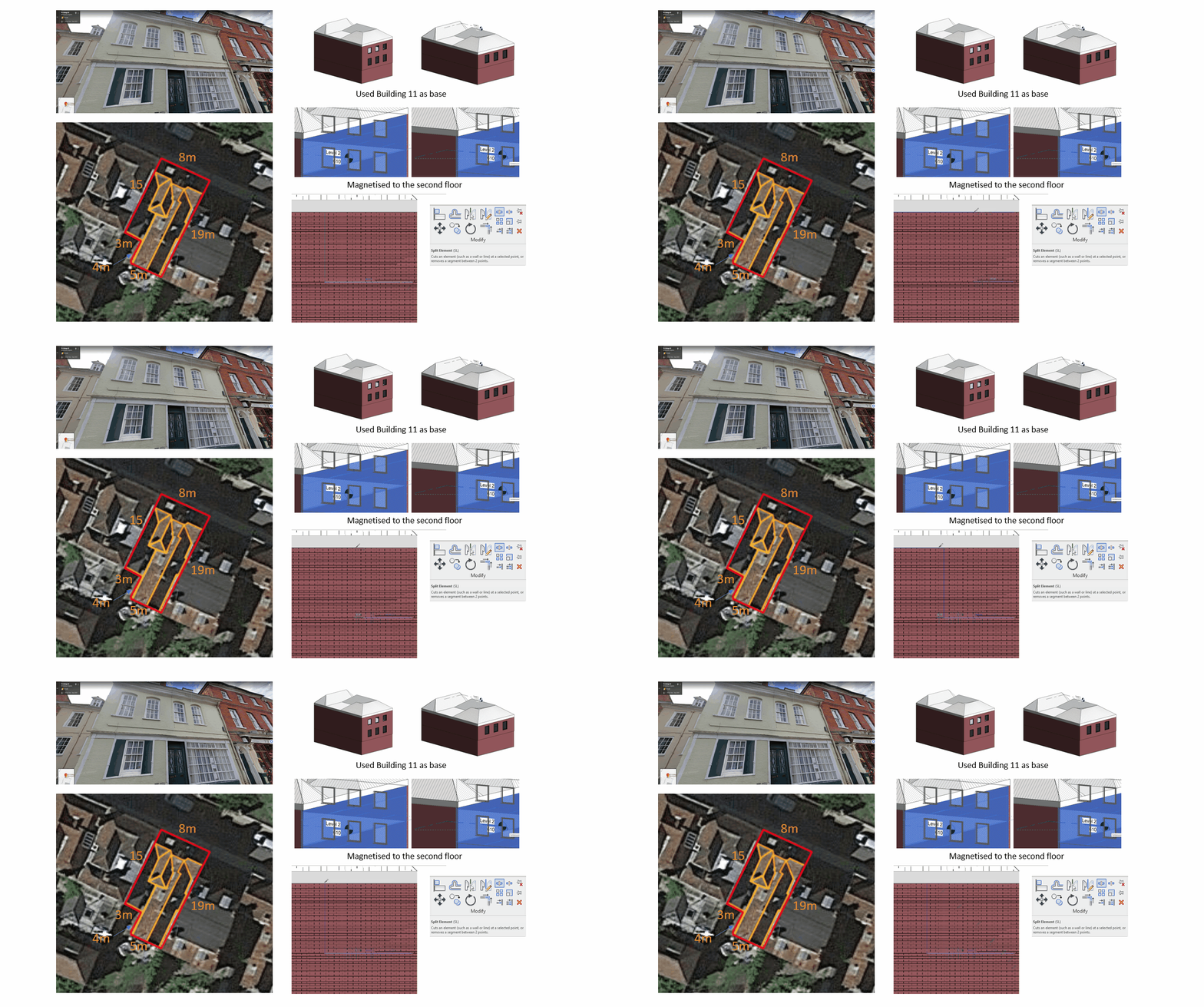
3.0 Building #6 | Revit
A summary of what I did for the 6th building. The main new area was that I used the split element tool to cut walls up in order to rearrange them.
3.1 Blocking out College Street | Blender
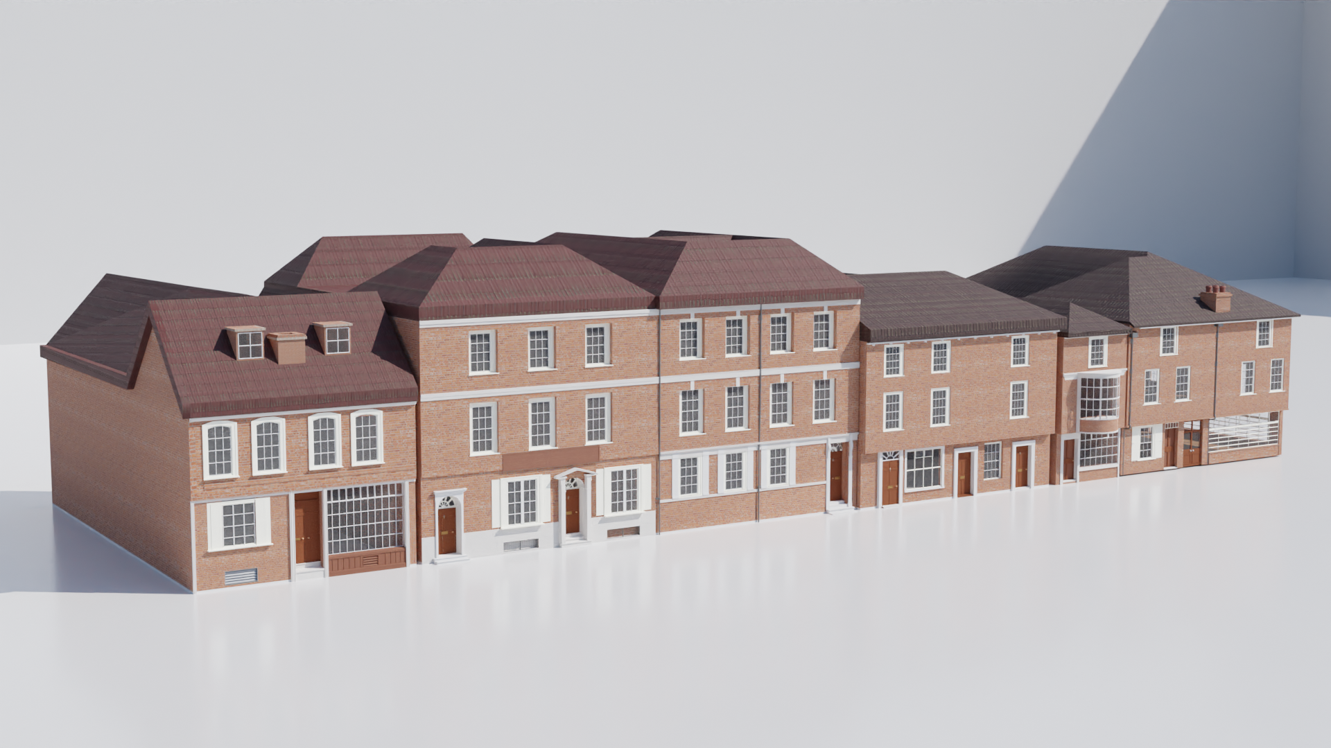
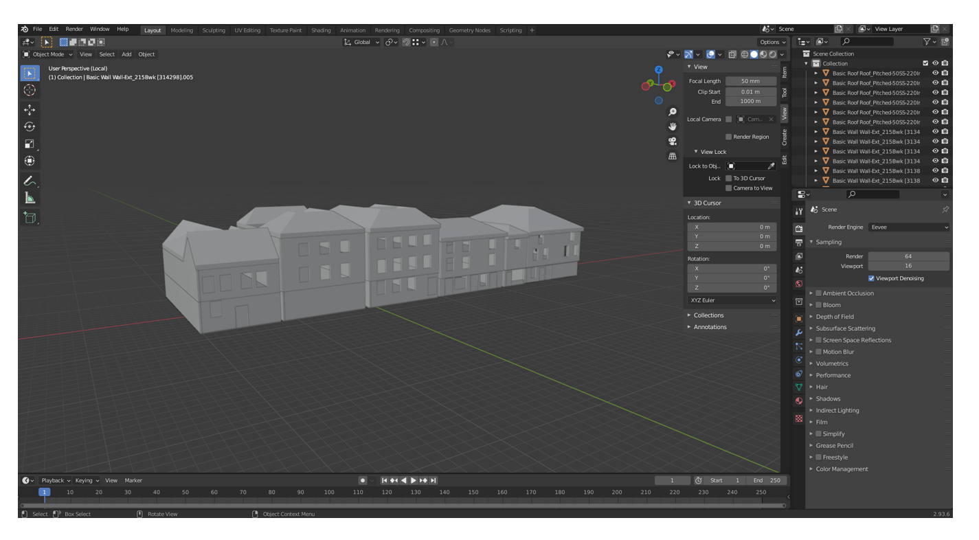
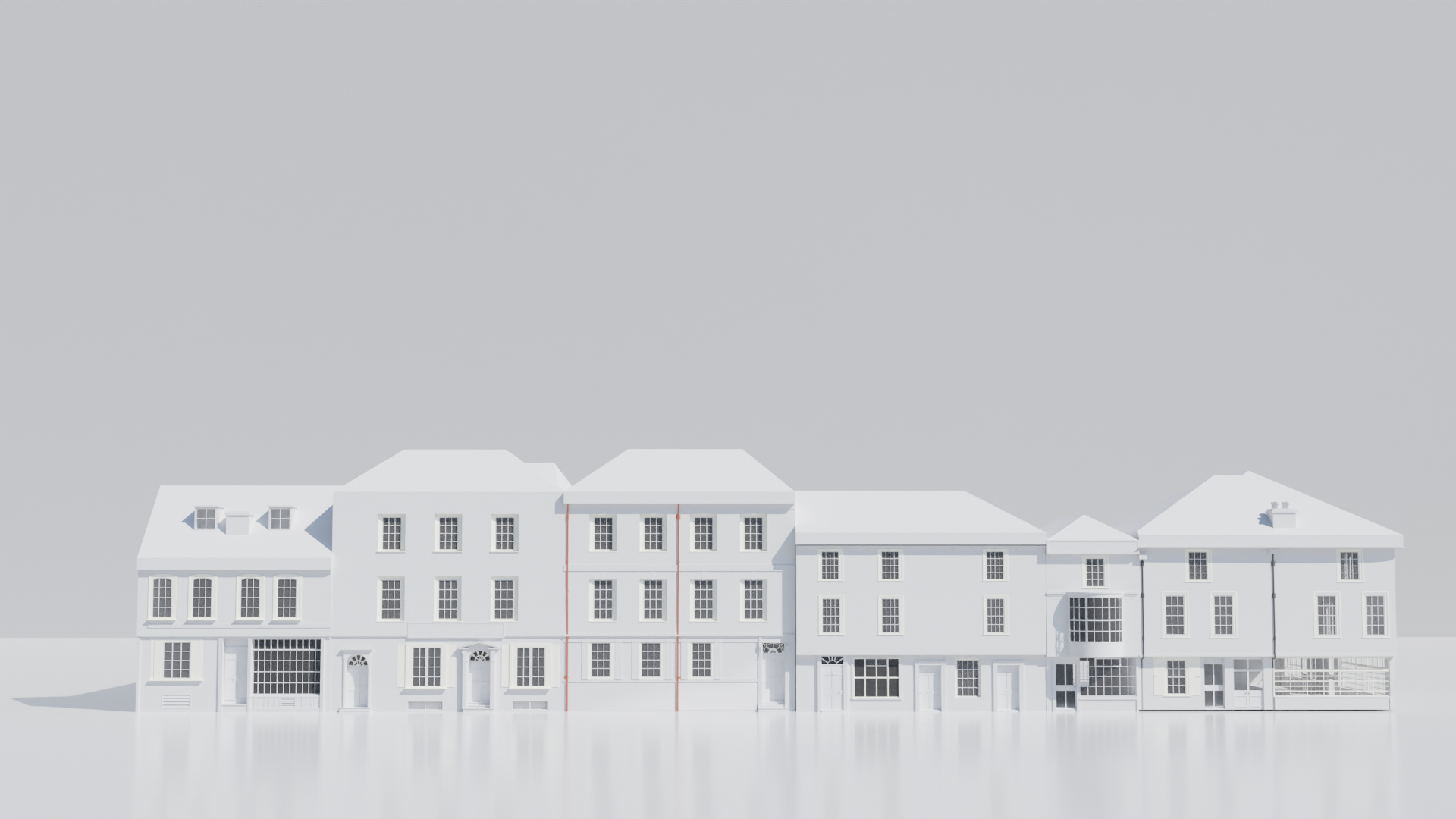
With all buildings finished, I assembled them in their order within a new Blende file, blocking out the street to gain a better visual of what has been made, and if the scaling of each building matched the real-life reference, to which I believe they do.
3.2 Building #1 | Window Making | Blender
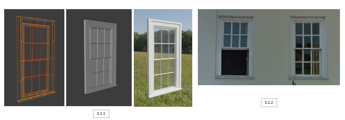
To start off, I began adding an image > reference [3.1.2], setting the opacity to 0.5 to allow me to match the scaling. With the plane adjusted to fit the reference image, I loop cut the plane to fit the number of glass cuts. A nice trick I found was the wireframe modifier [3.1.1], transforming the mesh into a wireframe by iterating over its faces, collecting all edges, and turning those edges into four-sided polygons, resembling a window grid shape. The next step was to make the general structure of the window, which was completed by extruding and re-scaling a pane aligned with the window bars. Finally, I duplicated the window face, separated it by the selection, removed the modifier, and applied a new material to the centre of the window that sets the Alpha to 0.03, giving a reflective glass effect [3.1.1].
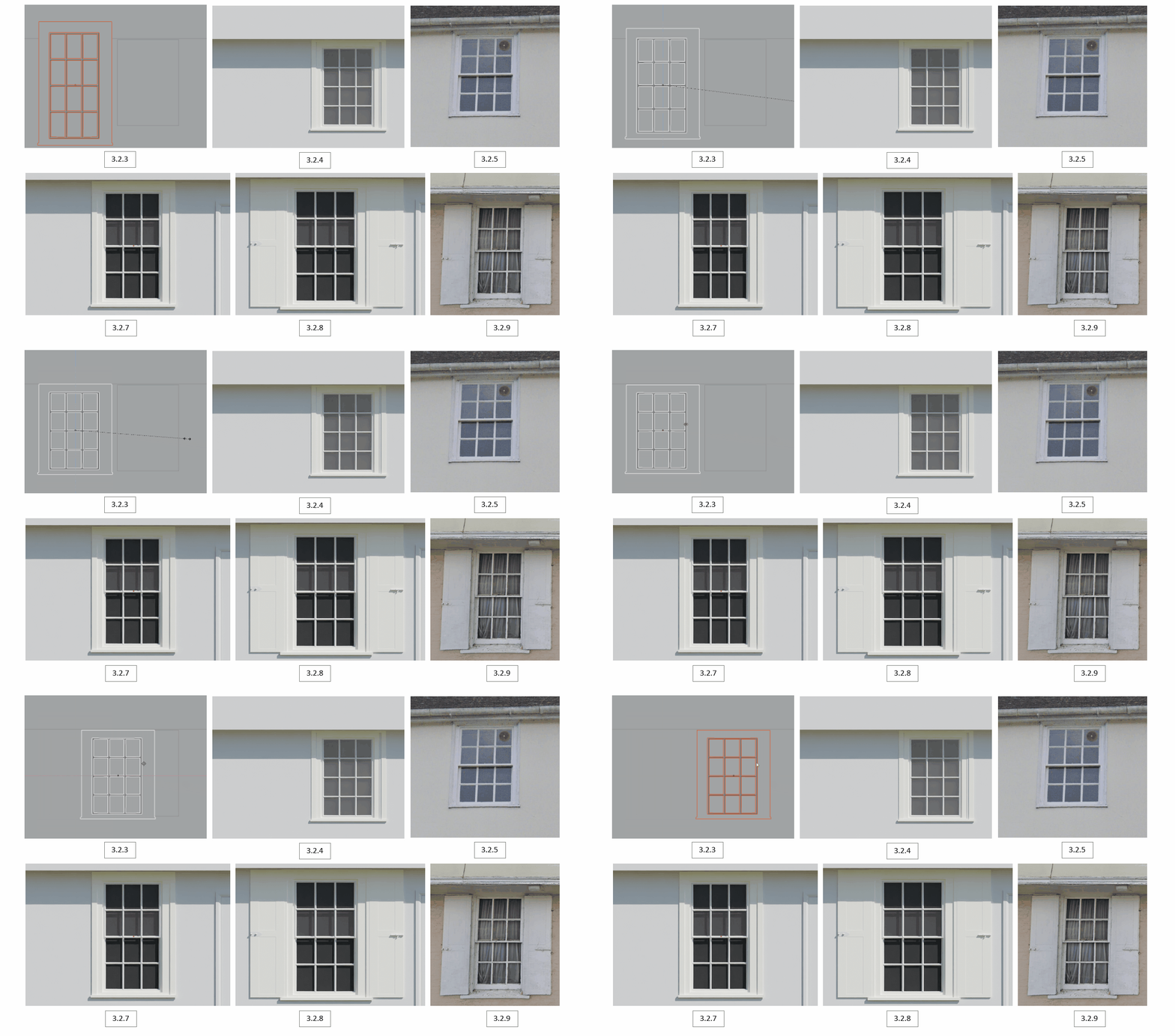
The top window was the same as the previous [3.2.7], but less in height. This was easily fixed by adjusting the height (Z-axis) and positioning the window accordingly [3.2.3] [3.2.4], resembling the reference image [3.2.5].
One of the windows located at the bottom had extra details, having shutters, a lock, and rectangular dents within the shutters. I believe that all these small details really help bring the houses to life [3.2.8], whilst resembling the reference image [3.2.9]
3.3 Door, Window & Details | Blender
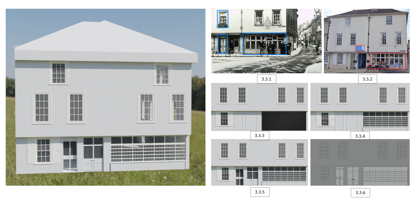
The old reference photo [3.3.1] was taken in 1915, meaning the building has most likely been renovated since after the death of Jane Austin, as her popularity grew and her last moments being in that street. This is the oldest and only photo I was able to obtain that displays the first building, so I didn’t have too much to go on for what has changed before the 1900s other than the general research of Georgian architecture.
Looking back at my reference image of the building I’m working on, I can see that there are a few differences [3.3.1] [3.3.2]. The windows on the second half of the building seem to have a grid-like pattern on the bottom layer, 21 to be specific. The blue sign located above the double door is not there. The single door design is different, having 4 white panels.
With all in mind, I started by making a Boolean > Difference cut that resembles the reference image [3.3.3]. This is where I created the large window, using the same wireframe modifier methods to create it [3.3.4]. This is followed by creating the doors [3.3.5], adding a plane, loop cutting and inserting faces to make the appropriate shapes, finished by extruding. The wireframe view of what has been created can be seen [3.3.6].
3.4 Pipes & Chimney | Blender
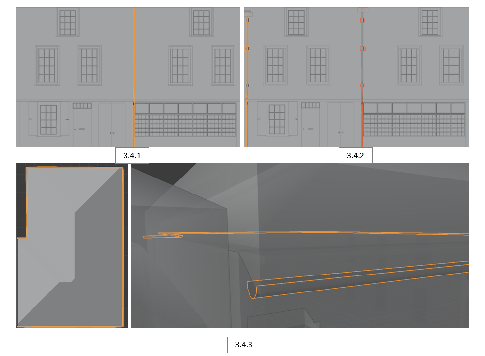
To create the pipes, I used a Bezier Curve as it’s easier to adjust the positioning, whilst retaining a smooth bend [3.4.1] [3.4.2]. Once positioned, the curve was converted to mesh as it allows me to edit the pipe, adding the extra 3D details. A very useful tool used throughout my project was the magnetic snap > to face/edge, making sure there were no gaps when attaching to the building. I noticed there was also a gutter (pipe under the roof that redirects rainwater down). This was made once again with a Bezier curve, converting to mesh and cutting it in half [3.4.3].
To create the pipes, I used a Bezier Curve as it’s easier to adjust the positioning, whilst retaining a smooth bend [3.4.1] [3.4.2]. Once positioned, the curve was converted to mesh as it allows me to edit the pipe, adding the extra 3D details. A very useful tool used throughout my project was the magnetic snap > to face/edge, making sure there were no gaps when attaching to the building. I noticed there was also a gutter (pipe under the roof that redirects rainwater down). This was made once again with a Bezier curve, converting to mesh and cutting it in half [3.4.3].
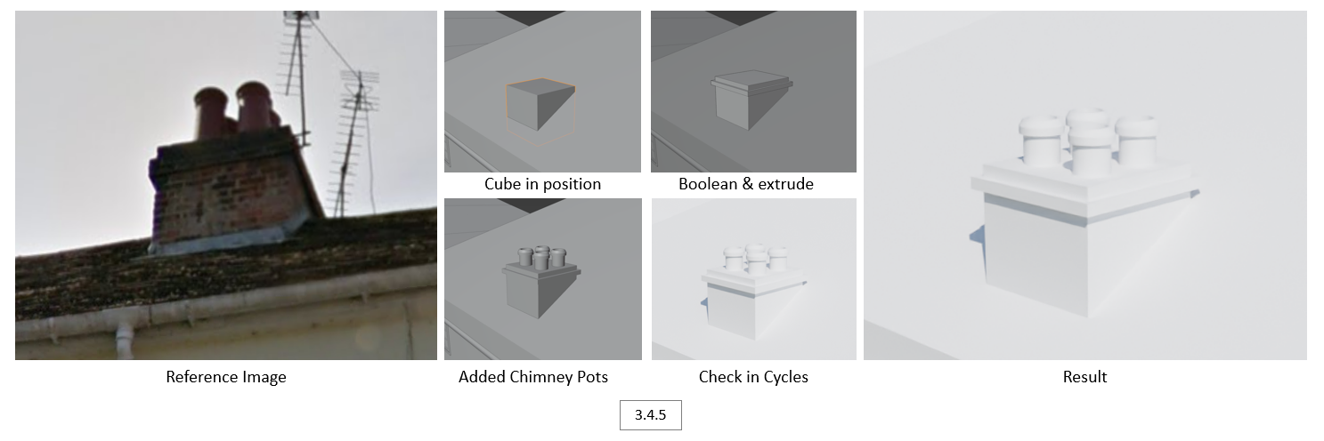
To create the chimney, I positioned a cube in the same area of the reference image, Boolean > difference cut it, extruded some details, and finally created some chimney pots [3.4.5].
3.5 Final Results | Blender
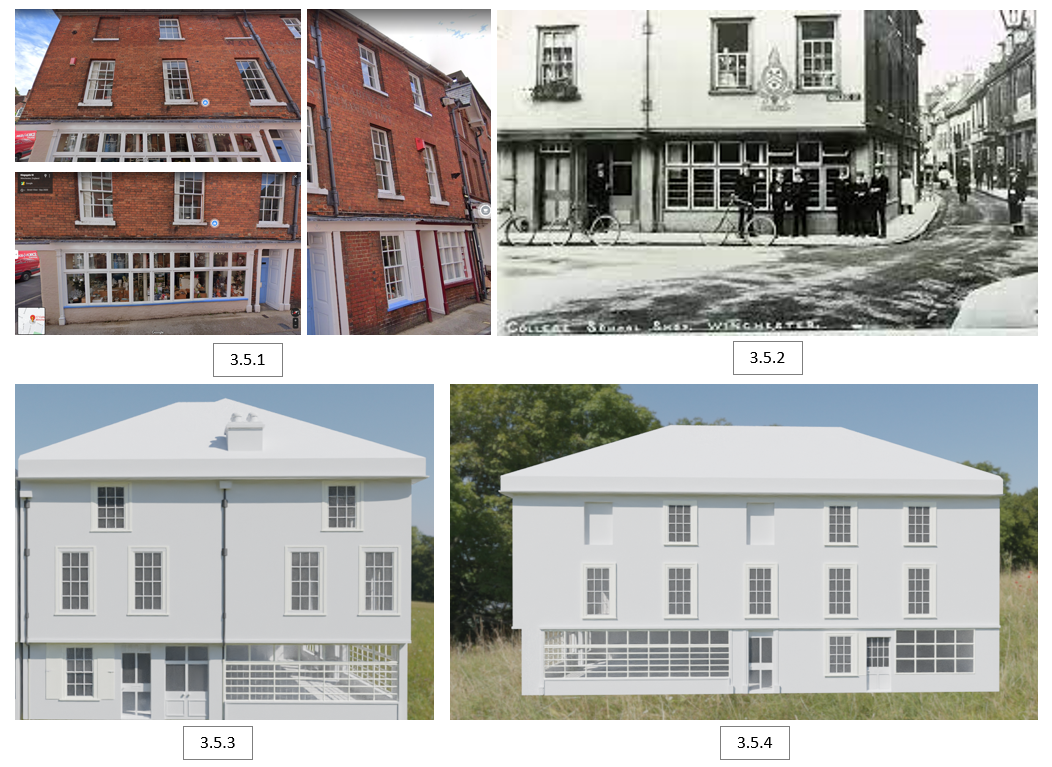
I believe that the building [3.5.3] [3.5.4] resembles the reference image very well [3.5.1], keeping in mind I also used the older photo [3.5.2] as a reference alongside the modern one.
3.6 Building #2 | Blender
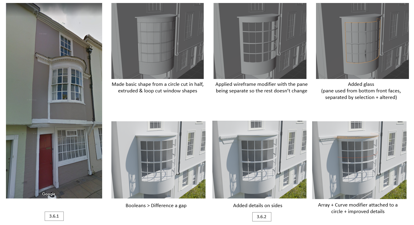
Using the reference image [3.6.1], I have displayed my step-by-step method of implementing the curved balcony. With the basic shape made from a circle, extruding, and loop cuts [3.6.2], I applied a wireframe modifier, added glass, Boolean > difference a gap, and finished by adding extra details using an array modifier attached to a circle [3.6.2].
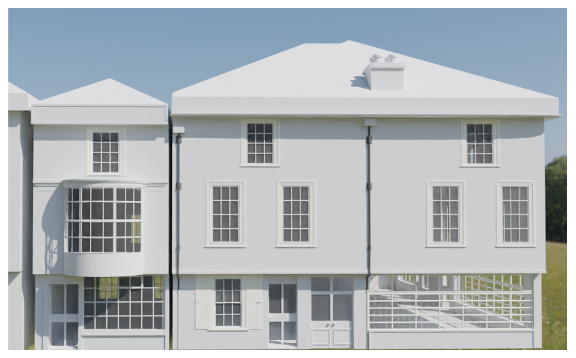
This is the final result of the second building. The door was copied over from the first one and modified to look different. The top window was also copied over as they are very similar. The bottom large window was made using the same methods (wireframe modifier + more faces).
3.7 Building #3 | Blender
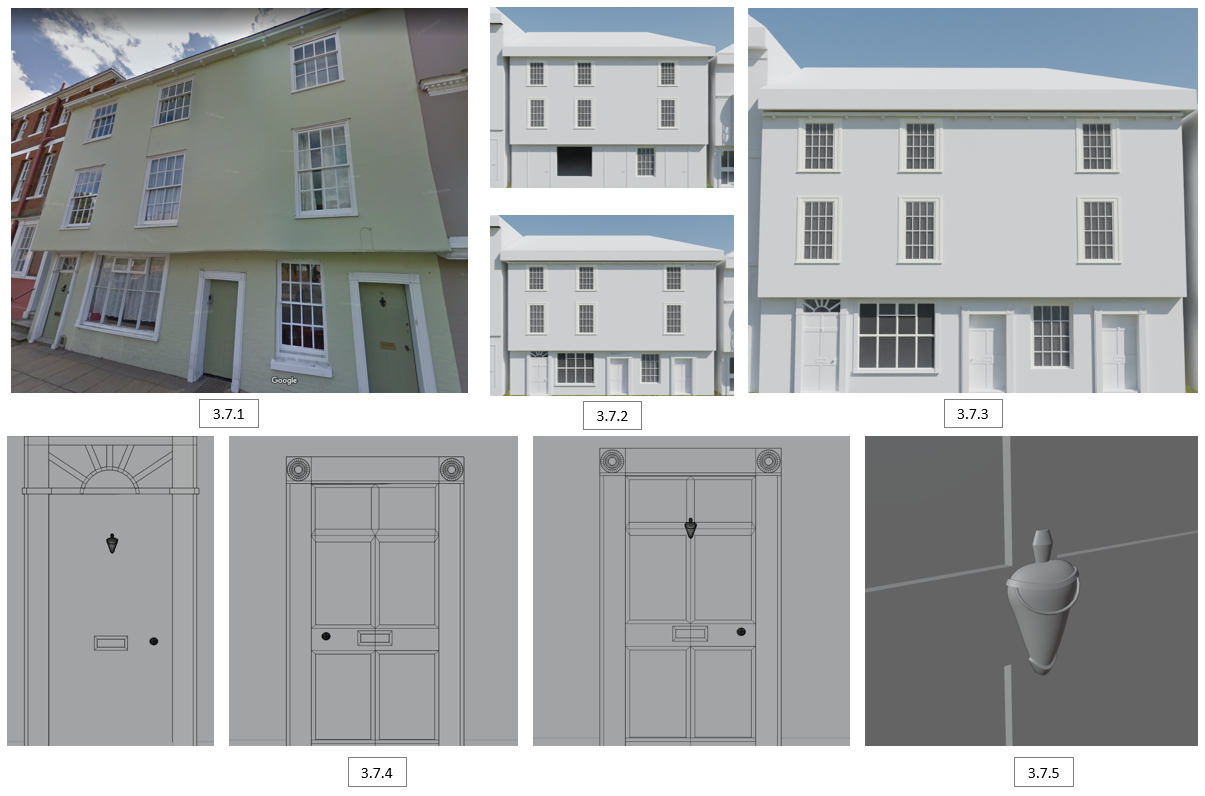
Using the reference image [3.7.1], I began by copying over the windows and adjusting them to size, whilst increasing the numbers of window tiles from 12 to 16 [3.7.2]. Copied over the doors that were already made and readjusted the designs with various extruding and loop cuts. The pattern on left [3.7.4] door was done with a circle, extruded to 3D, and extruded the top faces outwards. Borders around the doors were done with more extruding [3.7.4]. The top gutter pattern was done with an array modifier [3.7.3]. Finally, I noticed there was a door knock in the reference image, to which I decided to create [3.7.5], a combination of a UV sphere and Bezier curve.
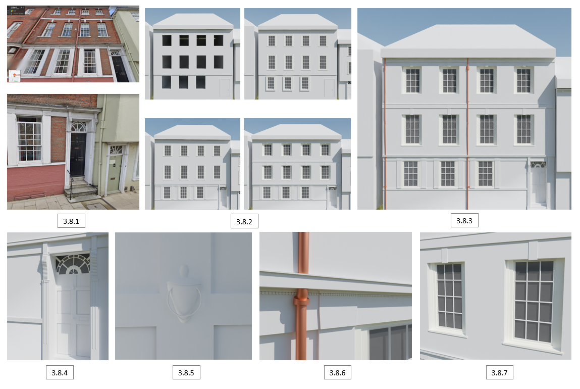
3.8 Building #4 | Blender
Using the reference images [3.8.1], I assembled the fourth house [3.8.2], copying and adjusting the windows and doors, whilst adding some extra 3D details of the structure. To finish, I used a Bezier curve to make new pipes, converted them to mesh and added the details [3.8.3]. I’ve added some highlights of what was done in terms of details on this building; creating a new semi-circle pattern with loop cuts [3.8.4], a new door knock [3.8.5], array modified pattern [3.8.6], and some extra brick details [3.8.7].
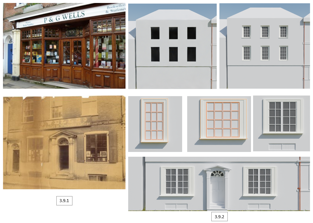
3.9 Building #5 | Blender
Using the reference images of both modern and old [3.9.1], I copied over some windows, whilst making new ones due to a different design [3.9.2]. This is followed by creating the door and triangular arch, having the face inserted, extruded, and bevelled at the edges, finishing by Boolean cutting the middle out [3.9.2]. Next were the vents, made with Boolean cut, copied pane, separate by selection, loop cut 10 by 10, and applied a wireframe modifier [3.9.2].
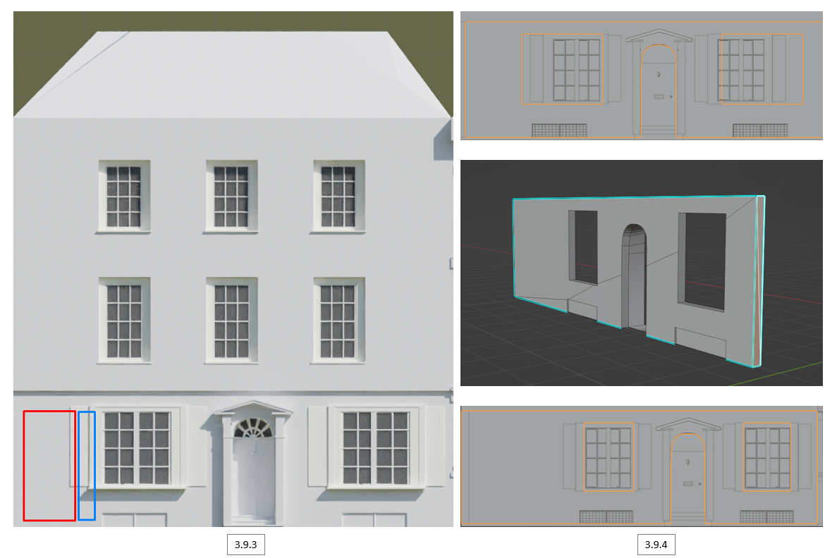
After making the first door and windows, there was not enough space to create another door with a gap [3.9.3]. This was solved by moving everything more to the right, however, it was not enough. I believed that the windows were slightly too large, making sure to thin them down to solve the issue.
First, I selected the faces of the window borders and moved them to the correct position, along with the windows. The next step was to simply reduce the wall length of the right side, move the wall with everything with it to the right, and finally extrude the left wall to fit [3.9.4].
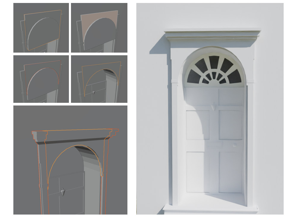
The next door was made by Boolean modifier with a semi-circle and cube to make an arch cut. The semi-circle glass pattern above the door was done with a circle cut in half, inserted faces to make the appropriate measured cuts, given glass material to selected faces and finally extruded to 3D.
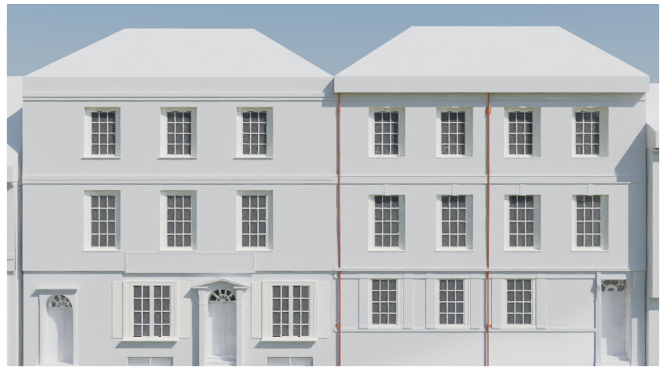
This is the final result of the second building. The door was copied over from the first one and modified to look different. The top window was also copied over as they are very similar. The bottom large window was made using the same methods (wireframe modifier + more faces).
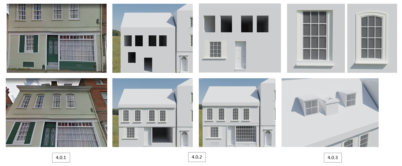
4.0 Building #6 | Blender
Using the reference images [4.0.2], I copied over existing windows and adjusted the edges with perspective warping to add a curve [4.0.1], resembling the real-life reference. This is followed by Boolean cutting a gap, creating a large window in its place [4.0.3]. Finally, I created the chimney and dormers (part of a roof that projects out vertically from the rest of the roof with a window) as shown in the references [4.0.4].
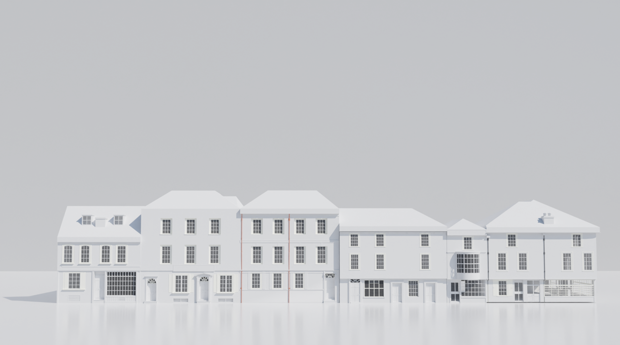
4.1 White Blocked Street Render | Blender
This is the full street done in terms of 3D modelling. I’ve connected them closer together to get a better visual of the street. I’m very proud of getting to this stage, seeing all the small details come together! The final step is to add the materials!

4.2 Brick Material | Mixer
For the texturing, I decided to use Quixel Mixer, texturing software that allows you to create and Utilize Physically Based Rendering (PBR) materials. Its biggest advantage is it allows you to procedurally create tileable textures and directly paint on 3d models utilizing a large free library of materials and the Quixel Megascans library.
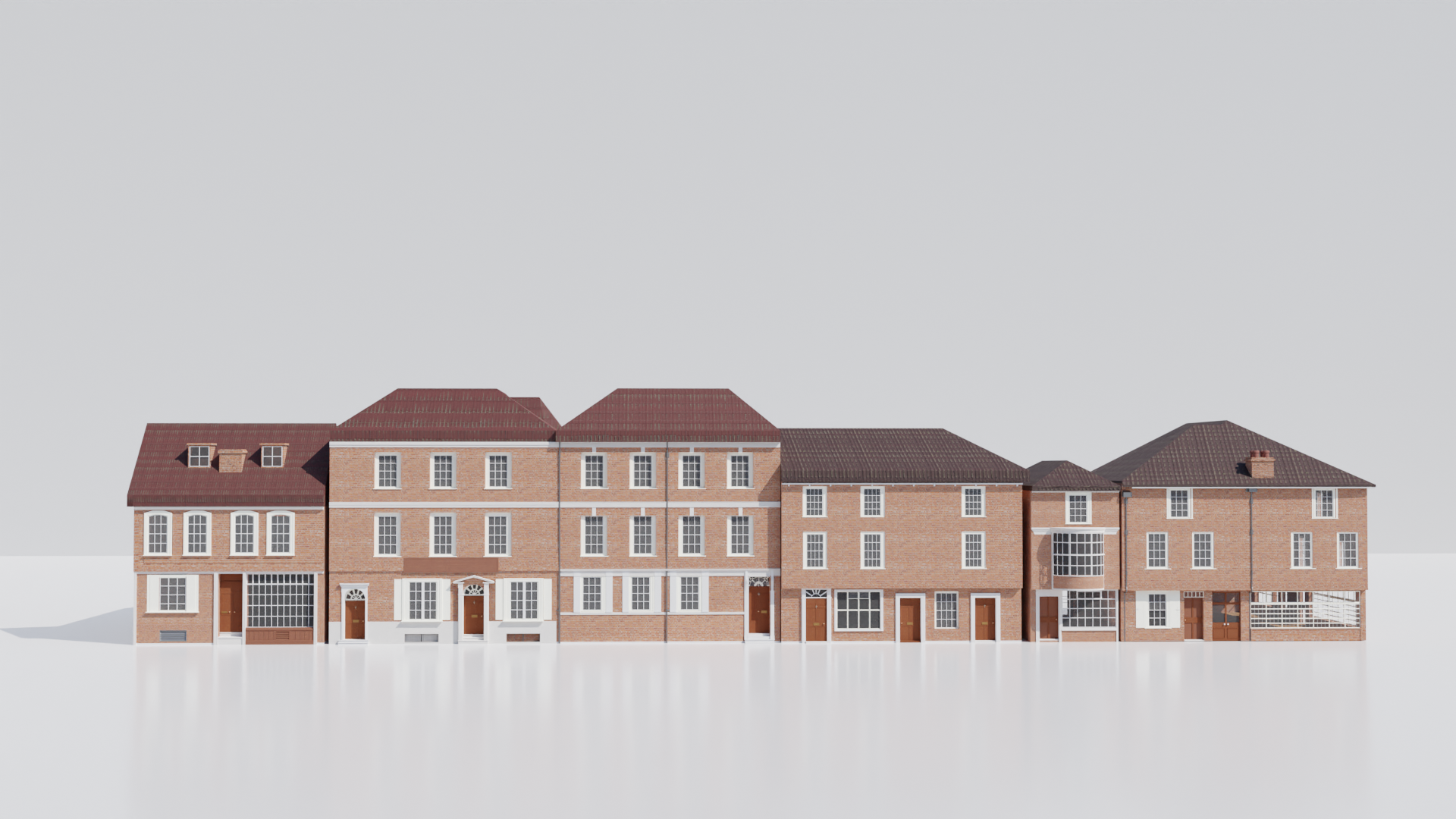
Within the library, I found 6 brick textures [4.2.1]. Removing 2 from the equation, I looked at how the brick textures would look like when applied [4.2.2]. This pattern is going to be referencing the real brick buildings [4.2.3], however, due to the buildings being based in the 1700s, I need to make them look somewhat new but not in quality condition.
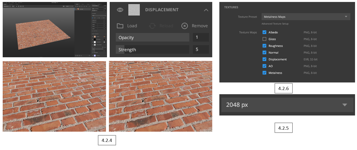
Originally, I wanted to strengthen the displacement to 5, making the 2d plane look more 3D by the bricks coming out more [4.2.4]. However, later I found that the faces would need to be loop cut quite a few times (50/75/100) to give the effect. This would significantly increase the poly count for such a small detail, therefore I decided to keep it a 2D plane.
I exported the texture as 2048 px to make sure the details of the brick were able to be seen in great detail and clarity [4.2.5]. There were options to go above, such as 4096 px and 8192 px, however, this would be too much in file size for every wall, and not benefit any more detail. Mixer was very useful as exporting came with all the necessary texture maps ready to download [4.2.6].
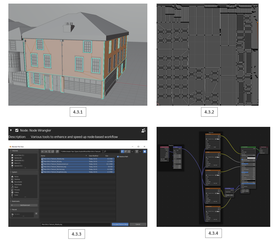
4.3 Principled Texture Setup | Blender
I began to Smart UV unwrap the first building by selecting all of the walls [4.3.1], arranging the faces in clear order on the UV map [4.3.2]. Using the addon Node Wrangler, I was able to use the short cut Ctrl + Shift + T to use the principled texture setup [4.3.3]. This allowed me to select all the exported maps and have them automatically set up and ready to use [4.3.4].
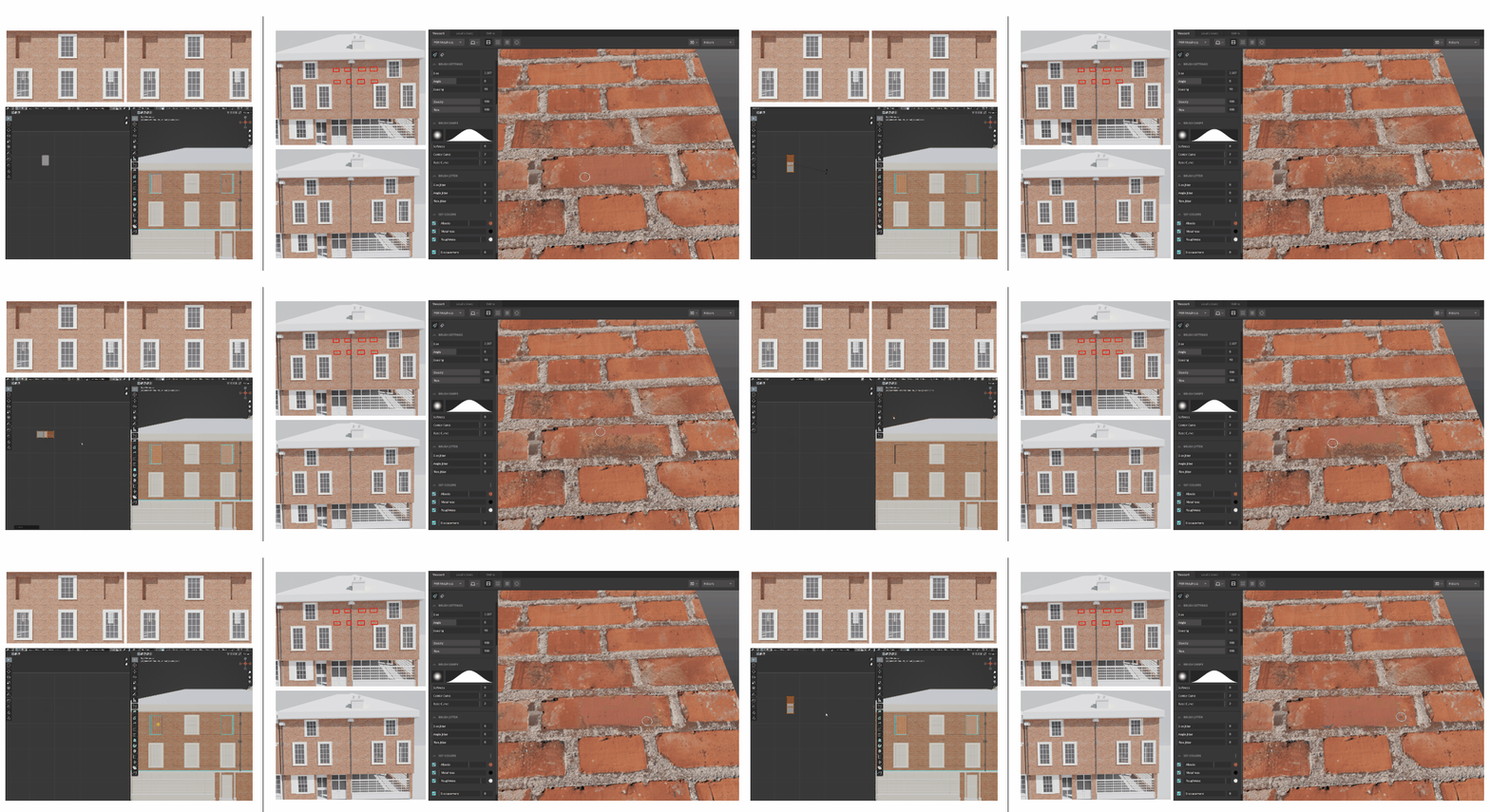
4.4 UV and Texture fixed | Blender
The first issue I had was that some of the bricks were rotated in the wrong direction [left side]. This was fixed by rotating the UVs of the selected faces 90 degrees.
The next issue I had was that the brick texture I chose was easily noticeable for its repetition, having the darker bricks being the main cause [Right side]. This was fixed by going back into Mixer and painting over the obvious dark bricks, re-exporting it and assigning the materials again, making it more seamless.
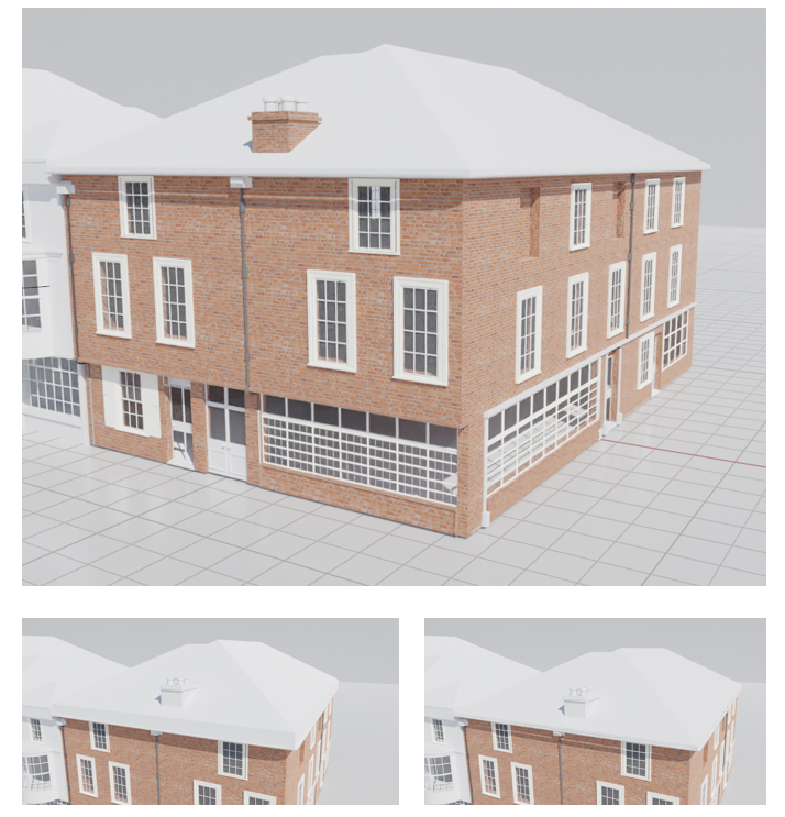
4.5 Bricked + Roof Adjustment | Blender
This is the bricked version of the first building, having seamless brick texture covering the walls. I also went ahead to readjust the overhanging roof, shorting it as I noticed it was too thick and far down.
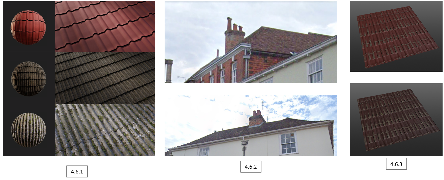
4.6 Roof Tiles Texture | Mixer
The next step was to make a roof tile texture. This was a bit more complex due to there not being a premade one that suits my references [4.6.2]. This meant I would need to blend 2 textures, one being a clean roof, the other being mossy, as roof tiles are common to have moss-covered all over (unless cleaned). I selected 3 tile textures [4.6.1], however, I only used the first and third ones due to the second one not showing too much detail when applied (shown later). With the 2 textures on the same layer, I combined the red roof tiles with the mossy ones, making it seem dirty whilst retaining the colour. In the end, a total of 2 roof tile textures [4.6.2], the brighter red being for the P & G Wells building (#4 & #5) and the last building (#6), and the darker ones for the rest (based of referencing).
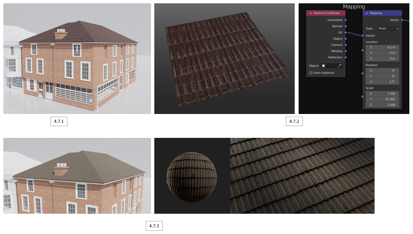
4.7 Applying Roof Tiles Texture | Blender
Still testing on my first building, I Smart UV unwrapped the roof and applied the darker roof tiles texture using the principal texture setup [4.7.1]. I had to scale the mapping of the X & Y to make sure the tiles were not stretched, making sure they are scaled to the correct proportion [4.7.2]. Going back to one of the old roof tiles textures I chose, this is the reason it didn’t really work as, without a proper displacement and 50/75/100 loop cuts, no detail can be seen. This is due to the complex shapes of the roofs, having many angles in various areas, making it hard to subdivide and apply the displacement map.
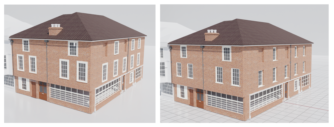
4.8 Window Readjustment | Blender
I noticed that not all the windows on each side had their frame coming out when looking into the building reference. A quick fix was done by readjusting the position of each window backwards, whilst extruding the bottom layer out.
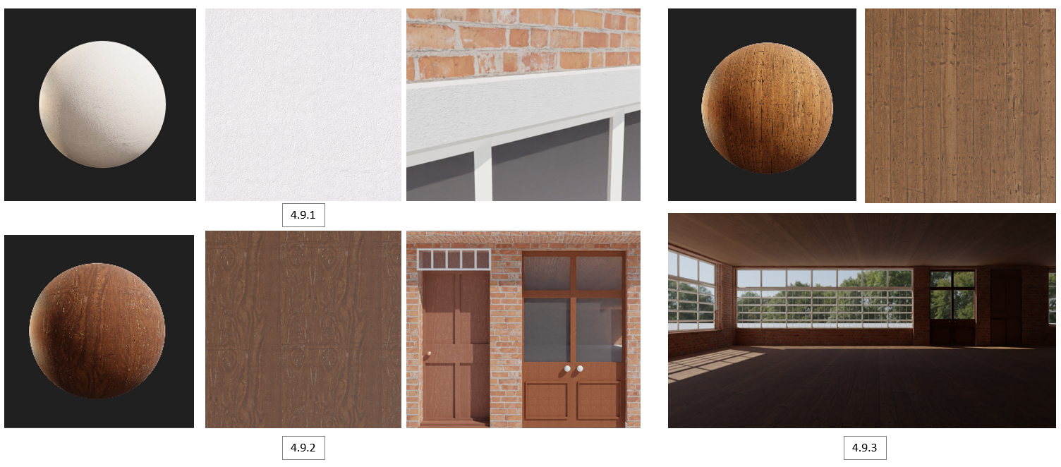
4.9 Photo-Realitic Materials | Mixer x Blender
From the Mixer library, I found a few more materials that I could use on all buildings. First, I used creamy white concrete [4.9.1] to apply on all the extensions of brick. The second was patterned wood [4.9.2], applying it to all the doors and making variations of colour tones. Finally, I wanted to make the interior, not brick, so I downloaded a wooden planks material and applied it inside the building [4.9.3]From the Mixer library, I found a few more materials that I could use on all buildings. First, I used creamy white concrete [4.9.1] to apply on all the extensions of brick. The second was patterned wood [4.9.2], applying it to all the doors and making variations of colour tones. Finally, I wanted to make the interior, not brick, so I downloaded a wooden planks material and applied it inside the building [4.9.3]From the Mixer library, I found a few more materials that I could use on all buildings. First, I used creamy white concrete [4.9.1] to apply on all the extensions of brick. The second was patterned wood [4.9.2], applying it to all the doors and making variations of colour tones. Finally, I wanted to make the interior, not brick, so I downloaded a wooden planks material and applied it inside the building [4.9.3]
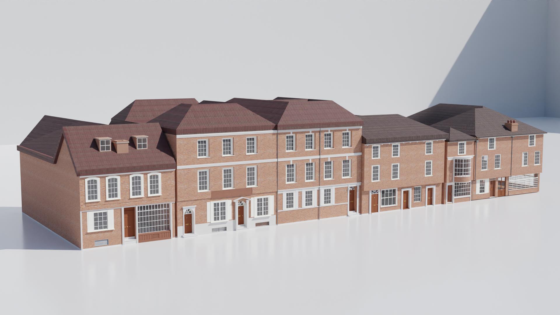
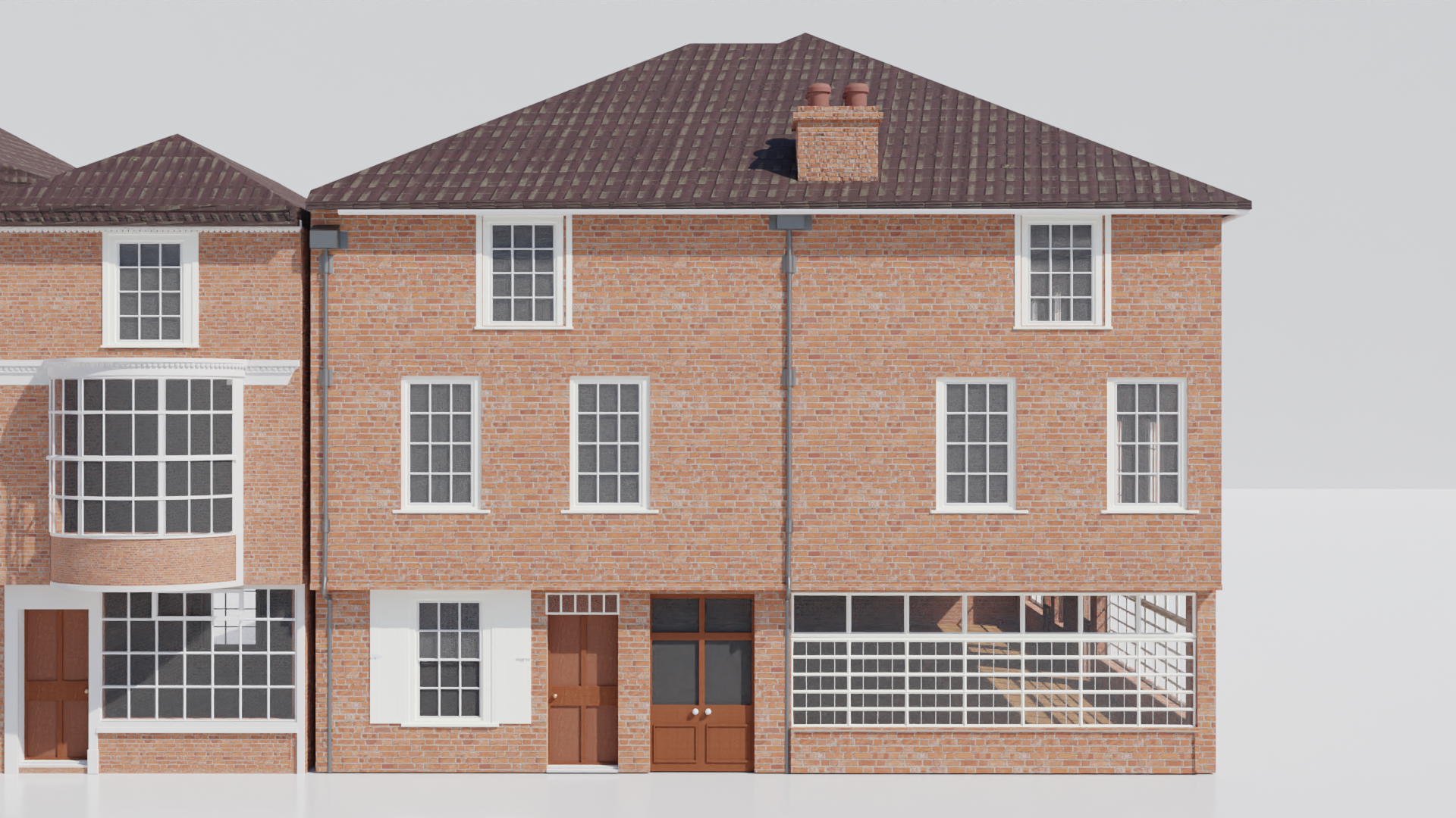
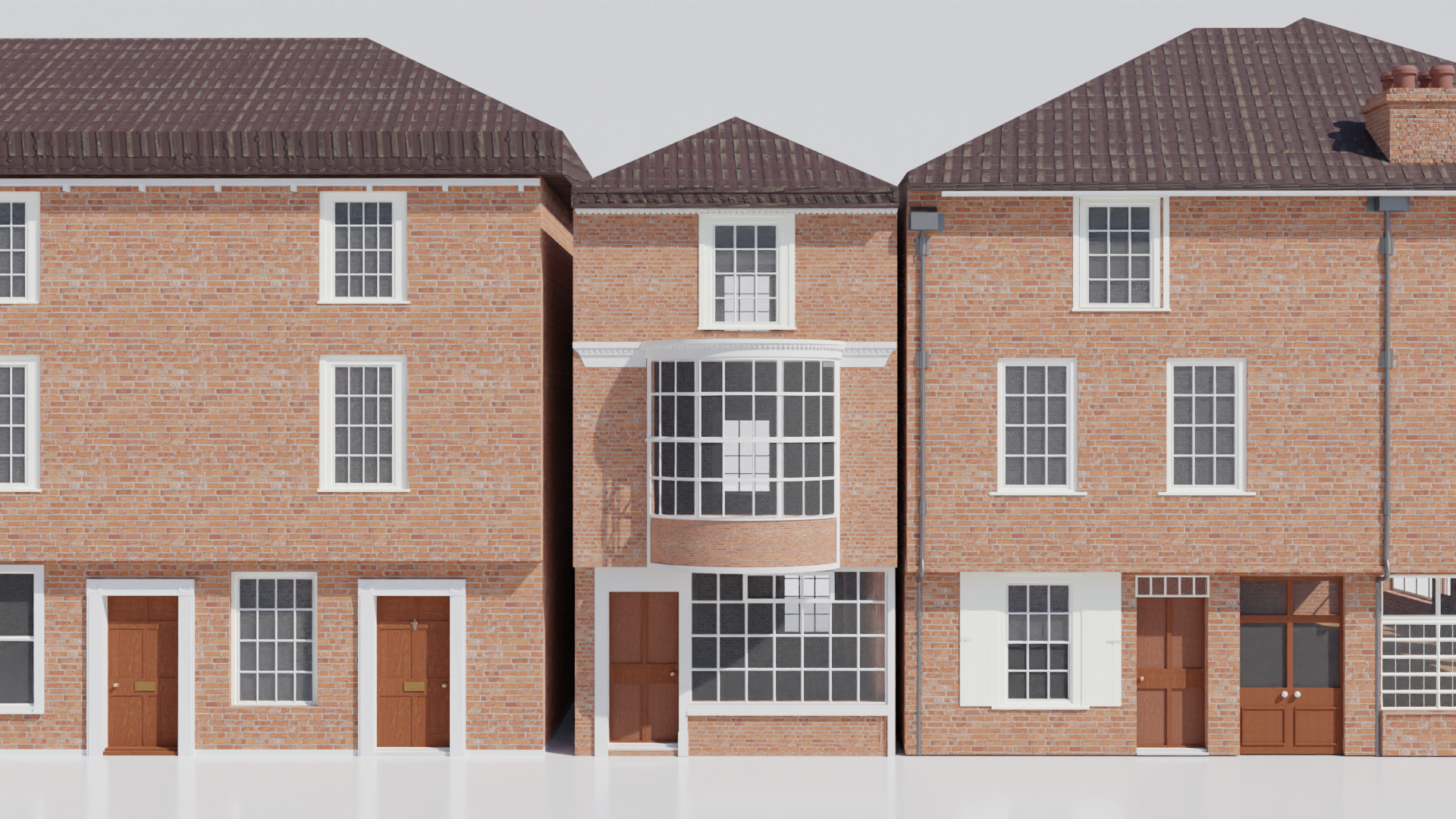
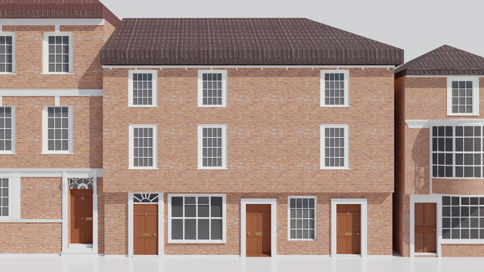
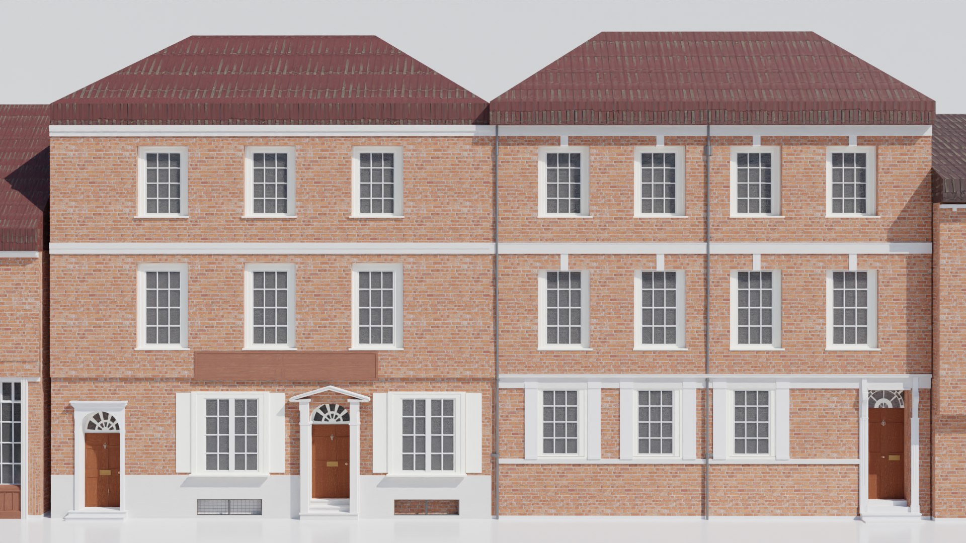

5.0 Conclusion | Client Project
Overall, I am extremely proud of this project! I’ve learnt that I’m able to produce high quality visual architectural buildings based on real-life referencing! Personally, this is a big step as this is my first-time creating buildings, with high detail, and not to mention based in the 1700s! As the project ends, the team will be in further contact with our client, Deborah Wilson, to apply all our buildings within an Unreal Project, recreating a realistic version of Jane Austen’s Winchester (1775 - 1817).
In terms of teamwork, I feel we worked quite well, even though we went out on separate paths! We created a Teams Group Chat, that includes our clients, to help each other out! I was the team leader for the project, so I tried my best to keep in contact with everyone during the project, scheduling meetings, making sure everyone is on track, and no one is left behind! Overall, I am very happy with the results of this project!